Table of Contents
Advertisement
Quick Links
Advertisement
Table of Contents

Related Manuals for horiba DS-72


Summary of Contents for horiba DS-72
- Page 1 Instruction Manual COND METER DS-72...
- Page 3 ■ Warranty and Responsibility HORIBA, Ltd. warrants that the Product shall be free from defects in material and workmanship and agrees to repair or replace free of charge, at option of HORIBA, Ltd., any malfunctioned or damaged Product attributable to responsibility of HORIBA, Ltd.
- Page 4 ■ EU Regulations ● Conformable standards This equipment conforms to the following standards: EMC: EN61326-1 Class B, Basic electromagnetic environment Safety: EN61010-1 RoHS: EN50581 9. Monitoring and control instruments Warning: This product is not intended for use in industrial environments. In an industrial environment, electromagnetic environmental effects may cause the incorrect performance of the product in which case the user may be required to take adequate measures.
- Page 5 REGULATIONS ● Authorised Representative in EU HORIBA UK Limited 2 Dalston Gardens, Stanmore, Middx HA7 1BQ, UK REGULATIONS ■ FCC Rules Any changes or modifications not expressly approved by the party responsible for compliance shall void the user's authority to operate the equipment.
- Page 6 SAFETY OPERATION ■ Hazard Classification and Warning Symbols Warning messages are described in the following manner. Read the messages and follow the instructions carefully. ● Hazard classification This indicates an imminently hazardous situation which, if not avoided, will result in death or serious injury. This signal word is to be limited to the most extreme situations.
- Page 7 SAFETY OPERATION ■ Safety Precautions This section provides precautions to enable you to use the product safely and correctly and to prevent injury and damage. The terms of DANGER, WARNING, and CAUTION indicate the degree of imminency and hazardous situation. Read the precautions carefully as it contains important safety messages.
- Page 8 SAFETY OPERATION ■ Product Handling Information ● Operational precautions Only use the product including accessories for their intended ● purpose. Do not drop, crash, or give any physical impact on the instrument. ● Do not immerse the instrument into alcohol, organic solvent, strong ●...
- Page 9 MANUAL INFORMATION ■ Description in This Manual This interprets the necessary points for correct operation and notifies the important points for handling the product. This indicates the part where to refer for information. HINT! This indicates reference information. ■ Original Language This is the English translation of an original Japanese document.
-
Page 10: Table Of Contents
Contents Chapter 1 OVERVIEW ................1 1.1 Description of Each Part ................ 1 1.1.1 Rear ....................1 1.1.2 Display .................... 1 1.1.3 Left Side ..................2 1.1.4 Right Side ..................2 1.1.5 Accessories ..................2 1.1.6 Operation Keys ................3 1.1.7 Icons (Icon Bar) ................ - Page 11 Contents 3.2.1 Cell Constant Setting ..............38 3.2.2 COND Measurement Unit Setting ..........39 3.2.3 Temperature Setting ..............40 3.2.4 Temperature Conversion Function Setting ........41 3.2.5 Alarm Setting ................42 3.2.6 Electrode Model Setting ..............44 3.2.7 Electrode Lot No. Setting .............. 45 3.3 COND Measurement ................
- Page 12 Contents 7.1.5 Measured by JP (OFF-LINE) ............63 7.1.6 Measured by JP (0mL-10mL (in container)) ......... 64 7.1.7 Measured by JP (10mL- (in container)) ........65 7.1.8 Measured by PPRC (CP) (Stage 1) ..........66 7.1.9 Measured by PPRC (CP) (Stage 2) ..........67 7.1.10 Temperature and Conductivity Requirements ......
-
Page 13: Chapter 1 Overview
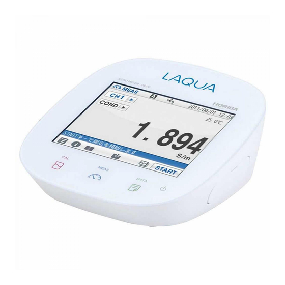
This chapter describes functions and basic operations of the instrument. 1.1 Description of Each Part 1.1.1 Rear CH2 reference electrode CH2 measurement electrode CH2 for temperature electrode 1.1.2 Display Status bar Touch panel Icon bar POWER key CAL key DATA key MEAS key DS-72... -
Page 14: Left Side
Instructs the usage of the instrument. Quick manual Instructs the operations of calibration and measurement. Ferrite core Attach this device to the AC adapter cable to reduce interference. *Clock battery (CR-2032) is put into the battery cover at the instrument bottom. HORIBA... -
Page 15: Operation Keys
Displays the calibration screen (CAL screen). MEAS Displays the measurement screen (MEAS screen). DATA Displays the data screen (DATA screen). The POWER key does not work for 10 seconds after the AC adapter is connected. Wait for a while after connecting AC adapter. DS-72... -
Page 16: Icons (Icon Bar)
Used to delete calibration data or the data saved in Trash box the instrument. Used to start and stop the operations of measurement and calibration, and to change to the Operation instantaneous value display. The icon label depends on the corresponding operation. HORIBA... -
Page 17: Status Icons
USB2 storage media. Shows that the instrument is connected with a printer with a Printer dedicated printer cable. *1: These icons appear when a USB cable is connected, but it does not always mean that the communication is conducted. DS-72... -
Page 18: Meas Screen
compensation The displayed temperature is the electrode electrode temperature (ATC). connection Not displayed: The displayed temperature is preset indicator value (MTC). Not displayed: An instantaneous value is displayed. HOLD indicator Blinking: In-process for HOLD Lighting up: HOLD completed. HORIBA... -
Page 19: Basic Operation Of Touch-Panel And Touch-Key
Keep a finger in contact with the screen and drag it on the screen. Used to search a setting item, or measurement data on the DATA screen. When a scroll bar is displayed on the right of the screen, you can scroll the screen by this operation. DS-72... -
Page 20: Function And Operation Of The Meas Screen
You can shift the screen to the digital, graph or analog screen by flicking it. Digital display If arrows, like , appear when you touch the screen, you can flick in the directions to switch the screen display. Graph display Analog display HORIBA... - Page 21 Lowers the range. Raises the range. The displayed range broadens. It allows you to check the wide-ranging variation of measurement values. Tap on the screen after the above operations, and the latest data will be displayed in optimized range. DS-72...
-
Page 22: Assembling The Electrode Stand
Chapter 1 OVERVIEW 1.4 Assembling the Electrode Stand Attach the stand shaft to the stand base. Stand shaft Attach the stopper and the stand arm to the stand shaft. Stand arm Stopper Stand base HORIBA... -
Page 23: Connecting The Electrode
Do not screw in it. 1.5.2 Temperature Connector Insert the temperature connector into the jack socket on the instrument. If the temperature connector is unconnected or the connection is wrong, the MTC set temperature is displayed as the liquid temperature. DS-72... -
Page 24: Connecting The Power Source
1. Set the DIP switch No. 6 to ON and No. 7 to OFF, and then set printer paper and ink ribbon. Keep the LF key held down. 2. Keep the SEL key held down. The printer prints output when the SEL key is being pressed. HORIBA... -
Page 25: Connecting The Personal Computer
If you change the transfer formats, power OFF both of the instrument and the personal computer once, and then turn ON them again. ・ For the details of communication commands, register with our website and see the free download page of manuals. DS-72... -
Page 26: Turn On The Power
Wait for a while after connecting AC adapter. ・ If the following message appears on the screen during operation, disconnect the AC adapter and then connect it again and power ON the instrument. ==DS-7X series memory manager== Exception failure occurred. Please detach AC adapter and restart. HORIBA... -
Page 27: Chapter 2 Before Measurement (Meter Set)
HOLD TYPE item. Select the measurement stability condition of the 6 types (EXACT, NORMAL, BRIEF, TIME, CUSTOMIZE, Manual) in the AUTO HOLD selection screen. To cancel the operation, tap to return to the previous screen. DS-72... -
Page 28: Custom Setting
Select the CUSTOMIZE of the Hold type to set the stability condition time and the stability condition value. Use the numeric-key screen to enter measurement variations as HOLD criteria for each measurement item. to return to the previous screen. HORIBA... -
Page 29: Sample Name Setting
Up to 10 characters can be input. The setting applies. To cancel the settings, tap to return to the previous screen. HINT! To delete a registered sample name, tap on the right of the sample name, enter noth- ing, and tap DS-72... -
Page 30: Interval Memory Setting
Enter Interval Time Display the Time item when select ON. on the right of the Time item. Enter the interval time in the numerical key screen. (Setting range: 1 to 999 sec.) The setting applies. To cancel the settings, tap HORIBA... -
Page 31: Usb Memory Setting
To cancel the operation, tap When the ejection is completed, a notice message will appears. Tap If you remove a USB memory from the instrument in a way other than mentioned above, data may not be saved correctly or data may be corrupted. DS-72... - Page 32 Do not remove the USB memory and do not disconnect the instrument power while this message appears. The instrument and USB memory are being accessed. When the format is completed, a notice message will appears. Tap HORIBA...
-
Page 33: Printer Setting
Auto printout item and select ON. Printout Layout This item allows you to change printing contents. on the right of the Printout Layout item. The printing format screen is displayed. to return to the previous screen. DS-72... - Page 34 When selecting CUSTOMIZE, you can select items that you want to print out among the GLP printing contents. But measurement values are always printed. BRIEF NORMAL GLP (CUSTOMIZE) COND measurement COND measurement COND measurement Measurement date Measurement value (Not be omitted) Measurement operator Settings Electrode Calibration operator Calibration data Signature HORIBA...
-
Page 35: Screen Settings
You can adjust the display brightness by tapping , or by dragging on the scale. on the right of the Display brightness item. When the screen becomes the desired brightness, tap To cancel the operation, tap to return to the previous screen. DS-72... - Page 36 (Setting range: 1 to 999 minutes) The set time applies. To cancel the settings, tap HINT! During the power saving mode, the LED lamp above the POWER key lights up. Press the POWER key to exit the power saving mode. HORIBA...
-
Page 37: Sound Setting
When the sound volume is set to 0, the instrument is in the mute mode. on the right of the Sound volume set- tings item. When the screen becomes the desired volume, To cancel the operation, tap to return to the previous screen. DS-72... -
Page 38: Language Setting
25 administrators or operators in total can be registered. on the right of the Security item. The User management screen is displayed. To cancel the operation, tap to return to the previous screen. on the right of the User management item and select ON. HORIBA... - Page 39 When the Security setting is ON, at least 1 administrator is required for the instrument. Administrators have to keep the password. We recommend registering 2 or more administrators. Administrator's names are marked with a star on the user selection screen. DS-72...
-
Page 40: User Entry/Info Change/Delete
When the Security setting is ON, at least 1 administrator is required for the instrument. Administrators have to keep the password. We recommend registering 2 or more administrators. Administrator's names are marked with a star on the user selection screen. HORIBA... - Page 41 When the Security setting is ON, at least 1 administrator is required for the instrument. Administrators have to keep the password. We recommend registering 2 or more administrators. Administrator's names are marked with a star on the user selection screen. DS-72...
-
Page 42: Date Setting
To cancel the operation, tap to return to the previous screen. Time You can set the time. on the right of the hour/min item. to set the time. To cancel the operation, tap to return to the previous screen. HORIBA... -
Page 43: Analog Output Adjustment
The Output value adjustment screen is dis- played. to adjust the analog output volt- age. To cancel the operation, tap to return to the previous screen. DS-72... -
Page 44: Temperature Sensor Calibration
Display "------", when not connecting the temper- ature sensor. on the right of the temperature sensor’s channel item. Enter the temperature with the numerical screen and tap when do not reflect the setting. HORIBA... -
Page 45: Resetting To Factory Defaults
Press and hold the POWER key for 2 seconds to turn ON. If you disconnect the AC adapter after powering OFF, the POWER key does not work for 10 seconds after the AC adapter is reconnected. Wait for a while after reconnecting AC adapter. DS-72... -
Page 46: Chapter 3 Cond (Conductivity) Measurement
"3.2.1 Cell Constant Setting" (P.38). 3.1.1 Automatic Calibration Setting Press the CAL key. and tap "CH2 CAL SET". A screen to select Cell Constant and Auto Calibration is displayed. on the right of the Auto Calibration item. HORIBA... -
Page 47: Calibration Of Standard Solution
When the calibration is completed, the HOLD indicator is lit up and the calibration state is displayed. after checking the calibration result to return to the CAL screen. To start the COND measurement, press the MEAS key. DS-72... - Page 48 The conductivity value of the standard solution used in the calibration process is the compensated value into the calibrating temperature by the temperature coefficient 2%/°C from the 25°C value. For more precise measurement, it is recommended to operate the calibration process at 25°C. HORIBA...
- Page 49 1332 12.15 105.9 81.00 1359 12.39 107.9 82.00 1386 12.64 109.8 84.00 1413 12.88 111.8 86.00 1440 13.13 113.8 87.00 1467 13.37 115.7 89.00 1494 13.62 117.7 90.00 1521 13.87 119.7 92.00 1548 14.12 121.8 94.00 1575 14.37 123.9 DS-72...
-
Page 50: Cond Measurement Setting
MEAS screen to set "CH2" and "COND". Press the CAL key. and tap "CH2 CAL SET". A screen to select Cell Constant and Auto Calibration is displayed. on the right of the Cell Constant item. The cell constant setting screen is displayed. HORIBA... -
Page 51: Cond Measurement Unit Setting
= 0.1 m 3.2.2 COND Measurement Unit Setting You can select S/m, S/cm or FIX (Unit is fixed at mS/cm as the COND measurement unit. on the right of the Unit item. Select S/m, S/cm or FIX. The selected unit applies. DS-72... -
Page 52: Temperature Setting
Solution Temperature Entry in MTC (Manual Temperature Compensation) Display the Temperature item when select MTC. on the right of the Temperature item. Enter the solution temperature on the numerical- key screen. The setting applies. To cancel the settings, tap HORIBA... -
Page 53: Temperature Conversion Function Setting
TEMP conversion item. Select "Manual" on the TEMP conversion screen. on the right of the Reference item. Enter any temperature value between 15°C and 30°C on the numerical-key screen. The setting applies. To cancel the settings, tap DS-72... -
Page 54: Alarm Setting
Upper limit value item. Enter an upper limit value on the numerical-key screen. To change the unit (mS/m, S/m, etc.), tap on the unit change key on the right of the numerical- key screen. The setting applies. To cancel the settings, tap HORIBA... - Page 55 To change the unit (mS/m, S/m, etc.), tap on the unit change key on the right of the numerical- key screen. The setting applies. To cancel the settings, tap Even if changing units (S/m, S/cm, FIX), the alarm set value is not changed. DS-72...
-
Page 56: Electrode Model Setting
Up to 10 characters can be input. The setting applies. To cancel the settings, tap HINT! To delete a registered electrode model name, tap on the right of the electrode model name, enter nothing, and tap HORIBA... -
Page 57: Electrode Lot No. Setting
Enter the electrode lot No. on the numerical-key screen. Up to 8 digits can be entered. To cancel the settings, tap HINT! To delete a registered electrode model name, tap on the right of the electrode model name, enter nothing, and tap DS-72... -
Page 58: Cond Measurement
HOLD indicator lights up. During instantaneous value measurement, or when a measurement value is held, you can store the measurement values by tapping the bottom of the screen. After the measurement is completed, tap to proceed to the next measurement. HORIBA... -
Page 59: Chapter 4 Sal (Salinity) Measurement
"CH2" and "SAL". and tap "CH2 MEAS SET". The SAL measurement setting items are displayed. on the right of the SAL type item. When the target for measurement is sea water, tap "SEA water." The setting applies. DS-72... -
Page 60: Sal Calibration Setting
When the calibration is completed, the HOLD indicator is lit up and the calibration result is dis- played. after checking the calibration result to return to the CAL screen. To start SAL measurement, press the MEAS key. HORIBA... -
Page 61: Sal Measurement Setting
Select PPT or %. The selected unit applies. 4.5 Temperature Setting The settings of temperature compensation and temperature conversion in COND measurement apply for SAL measurement (refer to "3.2.3 Temperature Setting" (P.40) and "3.2.4 Temperature Conversion Function Setting" (P.41)). DS-72... -
Page 62: Alarm Setting
When selecting ON the Alarm, lower limit item, the Lower limit value, tap on the right of the Lower limit value item. Enter an upper limit value on the numerical-key screen. The setting applies. To cancel the settings, tap HORIBA... -
Page 63: Electrode Model Setting
HOLD indicator lights up. During instantaneous value measurement, or when a measurement value is held, you can store the measurement values by tapping the bottom of the screen. After the measurement is completed, tap to proceed to the next measurement. DS-72... -
Page 64: Chapter 5 Resist (Resistivity) Measurement
(S/m or S/cm) of COND measurement setting ("3.2.2 COND Measurement Unit Setting" (P.39)). 5.3 Temperature Setting The settings of temperature compensation and temperature conversion in COND measurement apply for Resist measurement (refer to "3.2.3 Temperature Setting" (P.40) and "3.2.4 Temperature Conversion Function Setting" (P.41)). HORIBA... -
Page 65: Alarm Setting
Upper limit value item. Enter an upper limit value on the numerical-key screen. To change the unit (M•m, k•m etc.), tap on the unit change key on the right of the numerical- key screen. The setting applies. To cancel the settings, tap DS-72... -
Page 66: Electrode Model Setting
When the reading stabilizes, the value is held and HOLD indicator lights up. During instantaneous value measurement, or when a measurement value is held, you can store the measurement values by tapping the bottom of the screen. HORIBA... -
Page 67: Chapter 6 Tds (Total Dissolved Solids) Measurement
6.2 TDS Measurement Mode Setting For the TDS measurement, calculation using LINEAR, 442, EN27888, or NaCl can be selected. on the right of the TDS type item. The TDS type is displayed. Select the item to set. The setting applies. DS-72... -
Page 68: Input Tds Linear Value When Selecting Linear
"CH" is changes on the MEAS screen. Set the upper limit alarm to ON for the upper limit control of measurement value. Set the lower limit alarm to ON for the lower limit control of measurement value. Upper limit value Lower limit value HORIBA... -
Page 69: Input Upper Or Lower Limit Values
To change the unit, tap on the unit change key on the right of the numerical-key screen. The setting applies. To cancel the settings, tap 6.5 Electrode Model Setting The electrode model setting in COND measurement applies for TDS measurement (refer to "3.2.6 Electrode Model Setting" (P.44)). DS-72... -
Page 70: Tds Measurement
HOLD indicator lights up. During instantaneous value measurement, or when a measurement value is held, you can store the measurement values by tapping the bottom of the screen. After the measurement is completed, tap to proceed to the next measurement. HORIBA... -
Page 71: Chapter 7 Application Mode
This mode, you can save the measurement results only into a USB memory and print out them. If you need to save or print out the data, turn ON the "Simultaneously Memory" of "2.6 USB Memory Setting" (P.19) or "Auto Printout" of "2.7 Printer Setting" (P.21) in advance. DS-72... -
Page 72: Shift To Pharmacopeia Mode
Immerse the COND electrode in sample solution and tap to start the measurement. When measurement is completed, the conduc- tivity of the sample solution and the measure- ment condition are displayed as a measurement result. to return to the COND pharma- copeia mode screen. HORIBA... -
Page 73: Measured By Usp (Stage 2)
Immerse the COND electrode in sample solution and tap to start the measurement. When measurement is completed, the conduc- tivity of the sample solution and the measure- ment condition are displayed as a measurement result. to return to the COND pharma- copeia mode screen. DS-72... -
Page 74: Measured By Ep
Immerse the COND electrode in sample solution and tap to start the measurement. When measurement is completed, the conduc- tivity of the sample solution and the measure- ment condition are displayed as a measurement result. to return to the COND pharma- copeia mode screen. HORIBA... -
Page 75: Measured By Jp (Off-Line)
Immerse the COND electrode in sample solution and tap to start the measurement. When measurement is completed, the conduc- tivity of the sample solution and the measure- ment condition are displayed as a measurement result. to return to the COND pharma- copeia mode screen. DS-72... -
Page 76: Measured By Jp (0Ml-10Ml (In Container))
Immerse the COND electrode in sample solution and tap to start the measurement. When measurement is completed, the conduc- tivity of the sample solution and the measure- ment condition are displayed as a measurement result. to return to the COND pharma- copeia mode screen. HORIBA... -
Page 77: Measured By Jp (10Ml- (In Container))
Immerse the COND electrode in sample solution and tap to start the measurement. When measurement is completed, the conduc- tivity of the sample solution and the measure- ment condition are displayed as a measurement result. to return to the COND pharma- copeia mode screen. DS-72... -
Page 78: Measured By Pprc (Cp) (Stage 1)
Immerse the COND electrode in sample solution and tap to start the measurement. When measurement is completed, the conduc- tivity of the sample solution and the measure- ment condition are displayed as a measurement result. to return to the COND pharma- copeia mode screen. HORIBA... -
Page 79: Measured By Pprc (Cp) (Stage 2)
Immerse the COND electrode in sample solution and tap to start the measurement. When measurement is completed, the conduc- tivity of the sample solution and the measure- ment condition are displayed as a measurement result. to return to the COND pharma- copeia mode screen. DS-72... -
Page 80: Temperature And Conductivity Requirements
Chapter 7 Application Mode 7.1.10 Temperature and Conductivity Requirements (for non-temperature compensated conductivity measurement) Temperature (C) Required maximum (S/cm) Corresponding to USP (Stage1), EP, PPRC (CP) (Stage 1). HORIBA... -
Page 81: Chapter 8 Periodic Inspection Mode
(within 2%). Before the operation, set the cell constant written on the COND electrode referring to "3.1.1 Automatic Calibration Setting" (P.34). In this mode, the settings are changed as follows automatically. Unit: S/cm Temperature conversion: OFF Temperature setting: MTC, 20.0C DS-72... - Page 82 ・ Relative standard deviation (relative standard deviation at the repeated measurement (regulated value: within 2%)) An accurate thermometer is required for the measurement. Prepare an accurate thermometer and perform the measurement at 20C ±0.1C. The cell constant calculated in this check does not apply for cell constant calibration. HORIBA...
-
Page 83: Cond Checker (X-52) Mode
100.0 mS/m 10.00 mS/m 1.000 mS/m 0.000 mS/m Temperature check 0.0C 30.0C 60.0C 100.0C The conductivity measurement values displayed during in the above operations are not concerned with measurement. When all the check is completed, the result is displayed automatically. DS-72... -
Page 84: Comment Input
Indication error for each entry (regulated value ±0.4C). 8.2 Comment Input A comment can be entered up to 100 characters. Use this function to record periodical checks, etc. to use the function. To delete the content input previously, tap HORIBA... -
Page 85: Chapter 9 Data
"DELETE" is displayed under the ID number. to return the Measured data_All screen. "del" is indicated as the ID of the data to be deleted. After that, tap to execute deletion. To execute, tap . Not to execute, tap DS-72... -
Page 86: Measurement Data_Latest50
When you select User name, enter operator name and tap on the next screen. When you select Sample ID, enter sample name and tap item on the next screen. Search is performed and the result is displayed. HORIBA... -
Page 87: Copy All Meas. Data
9.6 Delete all meas. Data You can delete all measurement data saved in the instrument. on the right of the Delete all meas. Data to delete the all measurement data. To cancel the operation, tap in the Delete all meas. DATA screen. DS-72... -
Page 88: Chapter 10 Specifications
±0.5% ±1 digit of full scale Measuring principle Conversion from conductivity value Salinity Measuring range 0.00 PPT to 80.00 PPT (0.000% to 8.000%) (SAL) Resolution 0.01 PPT (0.001%) Measuring principle Conversion from conductivity value Measuring range 0.01 mg/L to 1000 g/L Resolution 0.01 mg/L HORIBA... -
Page 89: Default Settings
0.10 PPT to 10.00 PPT 0.30 PPT Resistivity variation width 1 to 100 digit 1 digit TDS variation width 0.1 mg/L to 100.0 mg/L 100.0 mg/L Interval memory function Enable/Disable Disable Interval memory Time setting value 1 second to 999 seconds 30 seconds DS-72... -
Page 90: Measurement Condition Default Settings (Can Be Set Per Operator)
Salinity Upper limit 0.00 PPT to 80.00 PPT 80.00 PPT measurement value (0.000% to 8.000%) condition Lower limit 0.00 PPT to 80.00 PPT 0.00 PPT value (0.000% to 8.000%) Measurement value unit PPT, % SAL type NaCl/SEA water NaCl HORIBA... - Page 91 1 to 999 minutes 60 minutes time Interface condition Volume 0 to 9 Sound setting STANDARD1, STANDARD2, Sound theme STANDARD1 AQUA, KYOTO Automatic Enable/Disable Disable printing Printer setting BRIEF/NORMAL/GLP/ Printing format NORMAL CUSTOMIZE Simultaneous USB memory Enable/Disable Disable memory DS-72...
-
Page 92: Options
Chapter 10 Specifications 10.3 Options This section lists spare and optional parts for the pH meter. These parts are possible through HORIBA distributors. Place an order specifying their name, model, and part number. Part name Part number Remarks AC adapter... - Page 93 For any question regarding this product, please contact your local agency, or inquire from the Customer Registration website (http://www.horiba.co.jp/register) February 2016 CODE: GZ0000260900E...
Need help?
Do you have a question about the DS-72 and is the answer not in the manual?
Questions and answers