Table of Contents
Advertisement
Quick Links
Advertisement
Table of Contents

Related Manuals for Marstair A2LCABINETMATCH


Summary of Contents for Marstair A2LCABINETMATCH
- Page 1 A2LCABINETMATCH TECHNICAL MANUAL 55008442-01...
-
Page 2: Table Of Contents
55008442-01 CONTENTS Section Page General Information 1A General Information 1B General Installation procedure SMC Condensing Units 2A Specification 2B Performance Data. 2C Mounting, Dimensions & Weights 2D Pipework Installation. 2E Pressure Testing 2F Evacuating 2G Electrical & Fuses 2H Refrigerant 2I Condensing Unit Wiring Diagrams 2J Electronic Valve Driver Interface 2K Electronic Valve Driver Parameters... -
Page 3: General Information
1 – GENERAL INFORMATION 1A GENERAL INFORMATION Installation must be carried out in accordance with the Marstair installation manual, EN 378 and national codes and guidance. 1. Installation work on this equipment to be completed by F Gas certified Technicians who are fully conversant with the appropriate Refrigeration and Electrical practices and have sound knowledge of current Industrial Safe Working practices. -
Page 4: General Installation Procedure
55008442-01 1B GENERAL INSTALLATION PROCEDURE Carry out “step by step” or full risk assessment Ensure that no sources of ignition are present during installation Only certified natural persons should be present during the installation Correct selection of tools and equipment compatible with A2L refrigerants. This should include the following: ▪... -
Page 5: Smc Condensing Units
55008442-01 2 - SMC CONDENSING UNITS 2A SPECIFICATION. Nominal cooling 1.24 1.53 1.78 2.26 2.96 4.17 5.26 5.95 capacity (-10°C evaporating temp & 32°C ambient temp) R454C 1 Ph (230V 50Hz) compressor load only (at nominal cooling capacity) Power (nominal) 0.72 0.83 0.98... -
Page 6: Performance Data
55008442-01 2B PERFORMANCE DATA. Evaporating temperature MODEL Ambient temperature 0.77 1.01 1.37 1.64 2.09 0.73 0.95 1.29 1.54 1.98 0.70 0.92 1.24 1.49 1.90 SMC 15 0.66 0.86 1.17 1.40 1.79 0.62 0.81 1.11 1.32 1.69 0.60 0.78 1.06 1.27 1.62 0.95 1.25... -
Page 7: Mounting, Dimensions & Weights
55008442-01 2C MOUNTING, DIMENSIONS & WEIGHTS. These units are designed to stand on a flat surface. If the unit is to be wall mounted the following kits are available. MRC+ 15-80 MRC+ 90-180 Mounting Bracket 55021100 55021101 Whether floor or wall mounted, it is essential that the mounting surface is capable of supporting the unit weight. Leave space around the unit for air circulation and access for installation and maintenance. - Page 8 55008442-01 SMC 15-90 (Dimensions in mm.) Model Dimensions Weight 1000 1000 1000 1000...
-
Page 9: Pipework Installation
55008442-01 2D GENERAL. Supplied Sweat connections Model Size Expansion Suction The installation section of the risk assessment template or equivalent should be carried out before commencing installation. When installing a split refrigeration system, all interconnecting refrigeration pipework must be manufactured, jointed, tested, insulated and installed in such a way as to ensure that damage cannot occur during normal, service and maintenance operations that may cause a rupture and subsequent leakage. - Page 10 55008442-01 2D2 SINGLE SPLIT SYSTEMS RUNNING ON EXPANSION LINES WITH EEV AND NO RECEIVER FITTED IN CONDENSING UNIT. MAXIMUM PIPE RUNS 80m maximum including 20m lift (50m SMC 15-20). There will be no significant loss of capacity for extended pipe runs provided pipes are correctly sized.
-
Page 11: Pressure Testing
55008442-01 2E PRESSURE TESTING The pressure testing section of the risk assessment template or equivalent should be carried out before commencing pressure testing. Pressure and leak testing of the system should be completed in accordance with EN 378. Note for single split systems with EEV in the condensing unit and no receiver only: The interconnecting pipework and evaporator are all on the low-pressure side of the system. -
Page 12: Refrigerant
55008442-01 2H REFRIGERANT Charging the system The charging of refrigerant section of the risk assessment template or equivalent should be carried out before commencing refrigerant charging. 1. Evacuate the system and interconnecting pipework ensuring the service valves are fully open. 2. - Page 13 55008442-01 SAGINOMIYA (XGE-4C) R454C: 210-220 psig (14.0-15.2barg) to achieve this turn the range adjusting screw clockwise (+) for increasing the setting value or counter clockwise (-) for decreasing the setting value. Pressure changes per 1 turn of adjusting screw: Pressure change: 10 … 25bar: Clockwise ~ +1.5 bar, counter clockwise ~ -1.5 ba...
-
Page 14: Condensing Unit Wiring Diagrams
55008442-01 2I CONDENSING UNIT WIRING DIAGRAMS... -
Page 15: Electronic Valve Driver Interface
55008442-01 ELECTRONIC VALVE DRIVER INTERFACE Note: The Electronic valve will be factory set to run at 6°C... - Page 16 55008442-01...
-
Page 17: Electronic Valve Driver Parameters
55008442-01 2K ELECTRONIC VALVE DRIVER PARAMETERS CONFIGURATION pLAN: 30 Network address 11 138 others: 198 A Refrigerant: 0 = User 13 140 0= user defined; Defined 1= R22 2= R134a 3= R404A 4= R407C 5= R410A 6= R507A 7= R290 8= R600 9= R600a 10= R717... - Page 18 55008442-01 Probe S2: 1 = CAREL 17 144 0= user defined 1= NTC CAREL CAREL NTC- HT high combined NTC SPKP**T0 5= NTC – LT CAREL low temperature 0 to 10V external signal A Auxiliary control: Disabled 18 145 0= user defined 1= Disabled 2= high condensing temperature protection on S3 probe 3= modulating thermostat on S4 probe...
- Page 19 55008442-01 Valve at fixed C S1 probe alarm manag.: 24 151 1= No action position 2= Valve forced closed 3= Valve at fixed posit. 4= Use backup probe S3 Valve at fixed C S2 probe alarm manag.: 25 152 1= No action position 2= Valve forced closed 3= Valve at fixed posit.
- Page 20 55008442-01 C Valve position in stand-by 91 218 0 = 25% 1…100% = % opening C start-up delay after defrost 40 167 A Pre-position time 18000 90 217 A Hot gas bypass temperature set point -85(-121) 200 (392) °C (°F) A Hot gas bypass pressure set point -20 (-290) 200 (2900)
- Page 21 55008442-01 C Low superheat alarm timeout (LowSH) 18000 43 170 (0= alarm DISABLED) C Low evap temp alarm timeout (LOP) 18000 41 168 (0= alarm DISABLED) C High evap temp alarm timeout (MOP) 18000 42 169 (0= alarm DISABLED) C High cond temp alarm timeout (High Tcond) 18000 44 171 (0= alarm DISABLED)
-
Page 22: Eco Design Information Tables
55008442-01 2L ECO DESIGN INFORMATION TABLES Model(s): SMC 15 S/P Refrigerant fluid(s): R454C Item Symbol Value Unit Evaporating temperature °C -10°C Parameters at full load and ambient temperature 32°C Rated cooling capacity 1.24 Rated power input 0.72 Rated COP 1.73 Parameters at full load and ambient temperature 25°C Cooling capacity 1.41... - Page 23 55008442-01 Model(s): SMC 40 S/P Refrigerant fluid(s): R454C Item Symbol Value Unit Evaporating temperature °C -10°C Parameters at full load and ambient temperature 32°C Rated cooling capacity 2.26 Rated power input 1.23 Rated COP 1.84 Parameters at full load and ambient temperature 25°C Cooling capacity 2.50 Power input...
- Page 24 55008442-01 Model(s): SMC 50 S/P Refrigerant fluid(s): R454C Item Symbol Value Unit Evaporating temperature °C -10°C Parameters at full load and ambient temperature 32°C Rated cooling capacity 4.17 Rated power input 1.75 Rated COP 2.38 Parameters at full load and ambient temperature 25°C Cooling capacity 4.49 Power input...
-
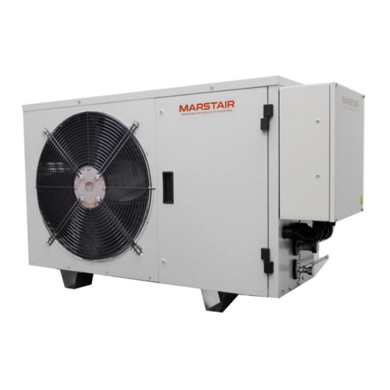
Page 25: Component Identification Smc
55008442-01 2M COMPONENT IDENTIFICATION SMC+... -
Page 26: Condensing Unit Maintenance
55008442-01 2N CONDENSING UNIT MAINTENANCE The refrigerant recovery section of the risk assessment template or equivalent should be carried out before commencing refrigerant recovery. Before engaging in any maintenance or repairs ensure Use of trained certified natural persons*. Well ventilated working environment. Use of a flammable gas leak detector. -
Page 27: Refrigerated Display Cabinet
55008442-01 3 – REFRIGERATED DISPLAY CABINET 3A GENERAL Ensure a Cabinet suitable for flammable refrigerants is used. Instructions for use with that cabinet must be followed, paying special attention the requirements of leak detection, alarms, and the procedures to follow should such a leak event occur. If the leak is identified as occurring outside the cold room, but inside a building or enclosure ensure adequate ventilation. -
Page 28: System Split Schematics
55008442-01 3C REFRIGERANT SYSTEM SCHEMATIC DIAGRAMS Single Split Match Run on Expansion line, Use SMC+ units with fitted EEV and no Receiver. Multi - Split Match Run on liquid lines, USE SMC+ unit with receiver and no fitted EEV. -
Page 29: System Selection Process
01484 405 666 | sales@marstair.com 5 – SPARES Products for spare parts, please ensure the use of official Marstair spares. Any spare parts taken from other companies, Marstair will not be responsible in case of any damage and will be out of warranty. - Page 30 55008442-01 INSTALLATION Question N/A YES NO Comments 1. Has correct PPE been selected? If yes go to question 2 If no stop assessment 2. Are suitable first aid facilities available? If yes go to question 3 If no stop assessment 3.
- Page 31 55008442-01 EVACUATION 29. Has a flammable gas leak detector been If yes go to question 30 energised and placed in a suitable location? If no rectify and reassess 30. Have all possible ignition sources been If yes go to question 31 removed from the work area? If no rectify and reassess 31.
- Page 32 If no rectify and reassess appropriate paperwork? 57. Identify source of leakage and recommence assessment procedure. This information is to be given to the end user along with the Marstair internal free volume assessment, and any other risks identified.
Need help?
Do you have a question about the A2LCABINETMATCH and is the answer not in the manual?
Questions and answers