
Related Manuals for Hasler HJ700


Summary of Contents for Hasler HJ700
- Page 1 Operating Guide Mailing Systems HASLER And Solutions ® America’s better choice HJ700 Inkjet Printer 08/19/2011...
- Page 2 Products presented in this guide are conform to requirements of directives nbr 2006/42/EG and 2004/108/EG. Hasler has implemented a program for the recycling of worn machines and machines at the end of their lifetime. Contribute in a res- ponsible way to the environmental protection by consulting your retailer internet site, or by contacting him.
- Page 3 Copyright © Copyright 2011 All rights reserved. No part of this manual may be reproduced or transmitted in any form or by any means, copied onto electronic media or translated into any language without the manufacturer's express written permission. The manufacturer is not liable for any damage resulting either from incorrect use or from repairs and modifications carried out by a third unauthorized party.
-
Page 4: Table Of Contents
Table of Contents Introduction ................9 1.1 Pictograms ................9 1.2 Notes for use of this manual............9 1.3 Terms and abbreviations ............10 1.4 System requirements ..............10 Safety notes ................11 2.1 General safety notes ...............11 2.2 Ink safety notice..............13 2.3 Location of the printer .............14 2.4 Disposal ................14 Scope of delivery and assembly.......... - Page 5 Additional Error Messages ..........125 8.5 Technical Support..............129 Consumables and Accessories ..........131 9.1 Consumables ............... 131 9.1.1 Standard inks for Hasler address printers......131 9.1.2 Cleaning Towels............... 132 9.2 Accessoires................133 9.2.1 Paper side guide ‘small’ ............ 133 9.2.2...
- Page 6 11 Appendix ................138 11.1 How to completely remove printer drivers from Windows Vista and Windows 7 ................138 11.2 How to completely remove printer drivers from Windows XP and Windows 2000 ................139 11.3 How to use a pre-installed printer driver ......141 11.3.1 USB connection..............141 11.3.2...
- Page 7 Table of Figures Figure 1: HJ700 overview frontside ................. 16 Figure 2: HJ700 overview rear side ................. 17 Figure 3: HJ700 overview frontside with open cover ..........18 Figure 4: Mounting I ....................20 Figure 5: Mounting II....................21 Figure 6: The operator panel..................23 Figure 7: Main display.....................
- Page 8 Figure 36: Update the printer driver................86 Figure 37: Update Driver Software Wizard ..............86 Figure 38: Select the driver source ................86 Figure 39: Ferrite with plastic case ................87 Figure 40: Adding TCP/IP Port.................. 88 Figure 41: TCP/IP Printer Port Wizard................ 88 Figure 42: IP address of the printer ................
-
Page 9: Introduction
If you are already familiar with the HJ700, it will make things easy if you to use this manual as a reference work. -
Page 10: Terms And Abbreviations
Pos: 11 /Bedienungsanleitungen/Geräte spezifisch/Drucker/1.4_Ü2_System requirements_ONLY_619 @ 2\mod_1272530190780_912.doc @ 17229 @ 2 1.4 System requirements The Hasler HJ700 is designed to be used in connection with a PC. To connect the HJ700 to the PC one free USB port or one free Ethernet (TCP/IP) port is required. The PC should be an up-to-date model and must have enough processing power and free disk space to run the Hasler Addressing Solutions Software. -
Page 11: Safety Notes
Safety notes Prior to initial operation, please carefully read the following instructions for the sake of both your own safety and the printer operating safety. Always observe any warnings and instructions directly attached to the device. Keep this manual available in order to be able to check back at any time. - Page 12 Pos: 18 /Bedienungsanleitungen/Geräte neutral/2.1h_Allgemeine Sicherheitshinweise_Hinweis Service @ 0\mod_1242737415895_912.doc @ 1746 @ Please contact your authorized Hasler dealer or service partner, for all questions relating to service and repair. In this way, you ensure the operational safety of your machine.
-
Page 13: Ink Safety Notice
2.2 Ink safety notice Keep ink cartridges away from children. If you get into skin contact with the ink, immediately clean off the ink under running water. In case ink has entered your eye, immediately rinse it with plenty of water. •... -
Page 14: Location Of The Printer
2.3 Location of the printer Be aware when installing the machine that it must stand on a smooth and level surface that is larger than the printer. When placing the machine, make sure that there is enough clearance around it, so that you can access all connections easily. -
Page 15: Scope Of Delivery And Assembly
Pos: 25 /Bedienungsanleitungen/Geräte neutral/3.2_Ü2_Delivery @ 0\mod_1242739526953_912.doc @ 1770 @ 2 3.2 Delivery The Hasler HJ700 is delivered in appropriate packaging so that it reaches its destination without damage via a regular mode of transport. Transportation and storage should be carried out in suitable condition. That means an ambient temperature between +10°C and +31°C at 20-80% relative humidity (non-... -
Page 16: Device Overview
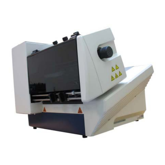
3.3 Device overview Pos: 28 /Bedienungsanleitungen/Geräte spezifisch/Drucker/AS-700/4.1_Geräteübersicht_AS-700/710_USB2.0 @ 3\mod_1296819973448_912.doc @ 29963 @ Pos: 24 /Bedienungsanleitungen/Geräte spezifisch/Labeler/L326/4.1_Geräteübersicht_L326 @ 0\mod_1250853155201_6.doc @ 2820 @ Figure 1: HJ700 overview frontside Paper feed ramp Separation adjustment knobs Paper side guides Transparent saftey cover Slide (Runner) -
Page 17: Figure 2: Hj700 Overview Rear Side
Figure 2: HJ700 overview rear side USB 2.0 interface to the PC for On/off switch sending print data Serial interface to the PC for status Power input module feedbacks and service purposes Ethernet (TCP/IP) interface for Fixing knobs for paper side guides... -
Page 18: Figure 3: Hj700 Overview Frontside With Open Cover
Figure 3: HJ700 overview frontside with open cover Transparent saftey cover (open) Cartridge carriage (shuttle) Ink cartridge Wiper for ink cartridge (part of the service station) Capping for ink cartridge Movable exit rollers (part of the service station) Pos: 29 /Bedienungsanleitungen/Geräte neutral/3.3_Ü2_Assembly @ 1\mod_1264168442358_912.doc @ 10763 @... -
Page 19: Assembly
(earthing)! Make sure that the on/off switch is set to off. Plug the power cable into the power input of the HJ700. Connect the cable to the power outlet. Pos: 32 /Bedienungsanleitungen/Geräte spezifisch/Drucker/AS-710/3.3.2_Ü3_How to mount the paper feed ramp and the side guides_AS-700/710 @ 2\mod_1270107752897_912.doc @ 14235 @ 3... -
Page 20: How To Mount The Paper Feed Ramp And The Side Guides
3.4.2 How to mount the paper feed ramp and the side guides • Mount the narrow paper side guide (inside) (1). Then mount the paper feed ramp (2) and either the narrow paper side guide (outside) (3) or the large (outside) one (not shown in Figure 4). -
Page 21: Figure 5: Mounting Ii
• To mount a paper side guide or the paper feed ramp, place the front bracket (A) into the slot of the contact plate and place the rear part (B) over a fixing screw. Then lock the fixing screw (see Figure 5). Figure 5: Mounting II Pos: 33 /Bedienungsanleitungen/Geräte neutral/4.0_Ü1_Description of device @ 0\mod_1246003073544_912.doc @ 1919 @ 1 User Manual Version 3.1... -
Page 22: Description Of Device
However, the application is not limited to this purpose. With the large print area of 180 mm / 7” the HJ700 is able to print onto a wide area. Pos: 36 /Bedienungsanleitungen/Geräte neutral/4.3_Ü2_Description of functions @ 0\mod_1250854288782_912.doc @ 2845 @ 2 4.2 Description of functions... -
Page 23: The Operator Panel
4.3 The Operator Panel Pos: 39 /Bedienungsanleitungen/Geräte spezifisch/Drucker/4.4_Operator_Panel @ 2\mod_1265967728349_912.doc @ 12018 @ Figure 6: The operator panel The operator panel is used to easily activate often required functions and select information from the main display. The operator panel is also used to navigate within the printer menus, in order to change printer and layout settings, run test modes and look up specific printer statistics. -
Page 24: Key Panel
4.3.1 Key panel Below is an explanation of how the different keys of the panel work: Main Function Ok (Online) Turns the printer online and confirms a selection in a menu Cancel (Offline) Turns the printer offline and exits the current menu level. - Page 25 Below is an explanation of how the different secondary functions of the arrow keys work: Secondary Function Quick key (Short) The printer will display Test and feed one Arrow up (Test Print) page and print the test pattern, using the current printer setting (e.g.
-
Page 26: Main Display
4.3.2 Main Display The main display shows you the most important information about your current print job at one glance. Pos: 42 /Bedienungsanleitungen/Geräte spezifisch/Drucker/4.4.3_Main_Display_Shuttle_Head_AS-700_ONLY_ONLY_619 @ 3\mod_1298994686644_912.doc @ 30610 @ J o b C u r r e n t : 1 2 3 4 5 6 7 ←... - Page 27 3: Shuttle speed This line shows the currently set shuttle speed. To change the speed select this line and use the arrow right or arrow left key to change the speed. Please note that the speed you can select is limited by the set print quality (see line 6).
- Page 28 7: Print direction This line shows the set print direction. Nor The print layout is printed in normal direction. Rev The print layout is printed 180° turned. Please refer to the section “Menu” of this manual, to get more detailed information about print direction. This setting can be locked, so that a print direction setting, send from the PC is ignored.
- Page 29 Additional display texts Under certain circumstances additional texts may be shown in the display. Please see chapter 11.10 Additional display texts, on page 154. Pos: 44 /Bedienungsanleitungen/Geräte neutral/5.0_Ü1_Initial start-up of the device @ 0\mod_1246014198984_912.doc @ 1931 @ 1 User Manual Version 3.1...
-
Page 30: Initial Start-Up Of The Device
Initial start-up of the device Pos: 45 /Bedienungsanleitungen/Geräte spezifisch/Drucker/5.0_print_first_test_page @ 1\mod_1263302633152_912.doc @ 10181 @ This section describes all the necessary steps to print the first test page with your Hasler HJ 700. Pos: 46 /Bedienungsanleitungen/Geräte neutral/5.2d_Ü2_How to power-on the device @ 0\mod_1250856526091_912.doc @ 2869 @ 2 5.1 How to power-on the device... -
Page 31: Installing The Ink Cartridge
Cartridge mounting The restraining lever ensures a safe contact between the ink cartridge and the electronics of the HJ700. Please do not force the ink cartridge to its final position by hand To avoid connection problems and damage, please install the cartridge as seen in Figure 8 and Figure 9. - Page 32 Do not touch the contacts or the nozzle plate of an ink cartridge. This may lead to reduced print quality. Ink cartridges We recommend to use only supported Hasler inks in connection with this printer. Refilled ink cartridges may result in bad printing quality and may damage the printer.
-
Page 33: How To Setup The Feeder
5.3 How to setup the feeder To setup the feeder you need to perform the following steps in this order: Adjust the separation Adjust the paper side guides Fill the feeder with material Adjust the paper feed ramp 1. Adjust •... -
Page 34: Figure 11: Separation Fingers
separation fingers Figure 11: Separation fingers 2. Adjust the • Loosen the fixing screws (C) of both paper side guides (see Figure paper side 12). guides • Move the two paper side guides apart. • Put in one medium in the feeder according to your desired print position. -
Page 35: Figure 12: Paper Side Guide Positions For C5 Envelope
Figure 12: Paper side guide positions for C5 envelope Figure 13: Positioning the material User Manual Version 3.1... -
Page 36: Figure 14: Position Of Paper Sensor
paper sensor position Figure 14: Position of paper sensor 3. Fill the • Put one piece of medium into the feeder. feeder with • Push the medium all the way to the separation fingers. material • Shingle the pile. • Put the pile into the feeder. -
Page 37: How To Adjust The Printer To The Material Thickness
5.4 How to adjust the printer to the material thickness To ensure a sharp, clean print quality and a safe material transport, you have to adjust the printer to the material thickness. Set the thickness adjustment knob to the following scale values: Scale value Material thickness... -
Page 38: Length Measurement Of The Medium
Pos: 54 /Bedienungsanleitungen/Geräte spezifisch/Drucker/AS-710/5.5_Ü2_Length Measurement of the Print Media_AS-700/710 @ 2\mod_1270557639681_912.doc @ 14311 @ 2 5.5 Length measurement of the medium The printer permanently controls the size of the fed media. Therefore the Hasler HJ700 needs to know the dimension of the medium at the beginning of a new print job. The dimension can either be measured manually or be sent by a PC software. -
Page 39: How To Set The Print Direction (Orientation)
Depending of the direction in which the products are fed into the printer, it could become necessary to turn the direction of the printed image by 180°. The Hasler HJ700 has a built-in feature that automatically turns the printed image by 180°. This adjustment can either be set directly in the printer menu, in the software application used to send the data to the printer or in the printer driver. -
Page 40: How To Perform A Test Print
5.7 How to perform a test print The test print function allows a fast test of the printer settings. The test print can be used to get a quick impression of the print quality of the inserted ink cartridge as well. There is no need to have a connection to a PC to use this function. -
Page 41: Printer Menu (Firmware V4.8)
Printer menu (firmware V4.8) Pos: 60 /Bedienungsanleitungen/Geräte spezifisch/Drucker/6.0_Introduction_Printer_Menu @ 2\mod_1265890955551_912.doc @ 11914 @ This chapter provides an overview of the menu structure of your Hasler printer, as well as a description for each single item of the menu. The index below shows the pages numbers for each item of the menu, as well as the structure of the printer menu. - Page 42 BEEPER .................... 59 AUTOM.PAGE REPEAT ................. 59 PAPER FEED RETRY ................60 JOB PARAMETERS ....................... 61 PRINT QUALITY....................61 TRANSPORT PARAM..................... 62 PAPER SPEED ..................62 SHUTTLE SPEED ................62 PRINTMODE ..................63 OPTIMIZATION .................. 63 EJECT DELAY[Sec] ................63 EJECT LAST PAPER ................
- Page 43 IP ....................73 Port No.: ..................74 MAC: ....................74 SM ....................74 GW ....................74 Monitor: ................... 74 Ink pack:..................74 SERVICE PRINT ....................75 Alignment Horiz................. 75 Alignment Vertic................75 Full Print Area ................... 75 Adjust Print Head................75 Cartr.
-
Page 44: Quick Menu
QUICK MENU The Quick key opens the following menu: Pos: 61.3 /Bedienungsanleitungen/Geräte spezifisch/Drucker/Menüpunkte Drucker/Quick Menü/Ü2_6001_PRINTER RESET_FW_4.8 @ 3\mod_1287746467437_912.doc @ 27909 @ PRINTER RESET The PRINTER RESET process is used when a print job needs to be cancelled. This process will clear the PC's spooler by first accepting all print data being sent from the PC application, deleting them and then resetting the printer internal buffer. -
Page 45: Clear Print Queue
CLEAR PRINT QUEUE Selecting CLEAR PRINT QUEUE will delete all print data within the printer buffer. It will not delete any print data waiting to be sent from the PC application during a print job. • Select CLEAR PRINT QUEUE in the QUICK MENU and hit the Ok key. -
Page 46: Paper Measurement
PAPER MEASUREMENT The printer will measure the paper width. Therefore please put one sheet of paper in the feeding position. After the measurement the printer will display the measured paper width. If you wish to lock the measured value in the printer, press the Ok button for three seconds (the PC software settings will not affect the printer set values). -
Page 47: Exchange Cartridge
EXCHANGE CARTRIDGE The cartridge moves out of its capping position, allowing a convenient exchange. After exchanging the cartridge hit the Ok key. If you inserted a new cartridge the printer will display RESET INK LEVEL?. Pressing the Ok key () will set the ink level to 100%. If you re-inserted the same cartridge press the Cancel key (). -
Page 48: Main Menu
MAIN MENU The Home key opens the main menu. Here you can access the following menus: PRINTER CONFIG. JOB PARAMETERS SERVICE LANGUAGE SETTING Pos: 61.15 /Bedienungsanleitungen/Geräte spezifisch/Drucker/Menüpunkte Drucker/Ü1/Ü1_1000_Menü_Drucker_PRINTER CONFIG. @ 0\mod_1253108079366_912.doc @ 3374 @ User Manual Version 3.1... -
Page 49: Printer Config
PRINTER CONFIG. This menu provides access to the following features. Pos: 61.16 /Bedienungsanleitungen/Geräte spezifisch/Drucker/Menüpunkte Drucker/Ü2/Ü2_1100_MAINENANCE @ 0\mod_1254483965167_912.doc @ 4041 @ MAINTENANCE Pos: 61.17 /Bedienungsanleitungen/Geräte spezifisch/Drucker/Menüpunkte Drucker/Ü3/Ü4/Ü3_1104_CLEANING CYCLE_Shuttle Head @ 0\mod_1254486713522_912.doc @ 4084 @ CLEANING CYCLE Here you can set the number of pages after which the printer performs a cleaning cycle. This means that the printer will stop printing, move the ink cartridge to the cleaning position and perform the purge the cartridge. -
Page 50: Figure 19: Keep Alive Function
KEEP ALIVE Here you can turn on the KEEP ALIVE maintenance function. This function helps to prevent the ink from drying inside the nozzles of the cartridge. During print jobs it can happen that some parts (nozzles) of an ink cartridge are not used on every page. -
Page 51: Adjustments
ADJUSTMENTS Pos: 61.22 /Bedienungsanleitungen/Geräte spezifisch/Drucker/Menüpunkte Drucker/Ü3/Ü4/Ü3_1302_ADJUSTMENT GAP @ 0\mod_1254831272021_912.doc @ 4329 @ ADJUSTMENT GAP Pos: 61.23 /Bedienungsanleitungen/Geräte spezifisch/Drucker/Menüpunkte Drucker/Ü3/Ü4/Ü4_130204_VERT.CORRECTION @ 0\mod_1254489912225_912.doc @ 4164 @ VERT. CORRECTION To optimize seamlessly transitions between the print lines of the moving printhead, the vertical offset can be calibrated. This adjustment becomes necessary if a gap or an overlapping area between the print lines becomes visible. -
Page 52: Figure 20: Carriage Correct
ADJUSTMENT STEPS Pos: 61.25 /Bedienungsanleitungen/Geräte spezifisch/Drucker/Menüpunkte Drucker/Ü3/Ü4/Ü4_130315_CARRIAGE CORRECT._AS-700/710 @ 0\mod_1254729851987_912.doc @ 4183 @ CARRIAGE CORRECT. Here you can set adjust a horizontal offset between the print of two carriage movements. The beginning of the print can be adjusted in 0.04 mm ( ’’) increments. -
Page 53: Figure 21: Adjust Tof
To make an adjustment press Quick (Test Print). The HJ700 will now print an adjustment page. Measure the distance between the paper edge and the printed bars (see Figure 21). Enter the measured distance in the printer menu and press the Ok key. -
Page 54: Boot Defaults
BOOT DEFAULTS All settings made in this menu apply for all print jobs and are retained after switching off the printer. • Select BOOT DEFAULTS in the PRINTER CONFIG. menu and hit the Ok key. You will be presented the following choices: Pos: 61.29 /Bedienungsanleitungen/Geräte spezifisch/Drucker/Menüpunkte Drucker/Menü_Drucker_Hinweis_BOOT DEFAULTS settings remain after printer reset @ 2\mod_1275288488760_912.doc @ 17703 @ BOOT DEFAULTS settings remain after printer reset The settings in the BOOT DEFAULTS menu cannot be changed by... -
Page 55: Communication
COMMUNICATION This feature is used to select the interface used for the communication between the printer and the PC. Select the interface and press the Ok key. Option Note The USB interface will be used. TCP/IP The TCP/IP interface will be used. dynamic IP fix IP dynamic IP... -
Page 56: Ink
Here the used ink type has to be selected. The listed parameters are optimized for the different Hasler inks. The parameters directly affect the electrical signals from the printer to the cartridge and are important for a correct ink drop formation. -
Page 57: Reset Ink Level
RESET INK LEVEL This feature is used to reset the calculated ink level of the cartridge. Choose yes for a reset. This reset should only be done when inserting a new, full cartridge. Otherwise the ink level bar in the display will not show a correct filling level. This feature is only accurate if it is used correctly. -
Page 58: Error Handling
ERROR HANDLING Select ERROR HANDLING in the PRINTER CONFIG. menu and hit the Ok key. You will be presented with the following choices: Pos: 61.42 /Bedienungsanleitungen/Geräte spezifisch/Drucker/Menüpunkte Drucker/Ü3/Ü4/Ü3_1701_SOFT FONT ERROR @ 0\mod_1254908138045_912.doc @ 4705 @ SOFT FONT ERROR This feature is used to set the printer response when it detects a PC font related error. Option Note cont. -
Page 59: Error Low Ink
ERROR LOW INK If the calculated ink level of a cartridge goes down to a certain value, the printer can warn the user or even stop the printing process. Option Note EMPTY CARTRIDGE Here you can set if the printer should stop or continue cont. -
Page 60: Paper Feed Retry
PAPER FEED RETRY This feature is used to set the behaviour of the printer when no more material is fed during a print job. Option Note try once The printer will try one time to feed material and if no material is fed, the printer will stop. -
Page 61: Job Parameters
JOB PARAMETERS This menu provides access to the following features. Pos: 61.49 /Bedienungsanleitungen/Geräte spezifisch/Drucker/Menüpunkte Drucker/Ü2/Ü2_2100_2101_PRINT_QUALITY @ 0\mod_1254485113011_912.doc @ 4075 @ PRINT QUALITY Here you can set the print quality, the resolution in dpi (dots per inch) the printer will use. Each of the eight print quality settings consist out of two numbers, one before the x and one after, e.g. -
Page 62: Transport Param
TRANSPORT PARAM. Pos: 61.52 /Bedienungsanleitungen/Geräte spezifisch/Drucker/Menüpunkte Drucker/Ü3/Ü4/Ü3_2201_PAPER SPEED_Only_AS-700/710 @ 0\mod_1254914049061_912.doc @ 4879 @ PAPER SPEED This feature is used to set how fast the product is transported forward in the printer. Choose a lower setting for very thick or very sensitive products. 30%, 40%, 50%, 60%, 70%, 80%, 90%, 100% Default: 100% Pos: 61.53 /Bedienungsanleitungen/Geräte spezifisch/Drucker/Menüpunkte Drucker/Menü_Drucker_Hinweis_Nicht "Lock"-bar @ 0\mod_1254823525509_912.doc @ 4313 @... -
Page 63: Printmode
PRINTMODE This feature is used to set if the printer should print on the forward and on the backward movement of the cartridge carriage, only on the forward movement or if that should be handled automatically. Option Note bidirectional The printer will print on the forward as well as on the backward movement of the cartridge carriage. -
Page 64: Figure 22: Difference Nor/Rev, Transport Direction
EJECT LAST PAPER This feature is used to set the transport behaviour of the printer for the last page of a print job. Option Note The printer ejects the last page of a print job. The printer holds the last page of a print job between the exit rollers. -
Page 65: Figure 23:Left Margin, Transport Direction
Pos: 61.63 /Bedienungsanleitungen/Geräte spezifisch/ LEFT MARGIN This feature is used to set the left margin of the print area in [mm]/[inch]. Figure 23:LEFT MARGIN, transport direction Pos: 61.64 /Bedienungsanleitungen/Geräte spezifisch/Drucker/Menüpunkte Drucker/Ü3/Ü4/Ü3_2305_TOP MARGIN_Shuttle Head @ 1\mod_1259843902972_912.doc @ 8119 @ TOP MARGIN This feature is used to set the top margin of the print area in [mm]/[inch]. -
Page 66: Character Spacing
CHARACTER SPACING This feature is used to set the spacing between the individual characters from 0 to 90 dots. Default: 0 Pos: 61.69 /Bedienungsanleitungen/Geräte spezifisch/Drucker/Menüpunkte Drucker/Menü_Drucker_Hinweis_Plain text output only @ 2\mod_1268922052172_912.doc @ 13590 @ Plain text output only When using a modern Microsoft Windows computer with layout software like "Flex Mail"... -
Page 67: Hex To Ascii
HEX TO ASCII Conversion from HEX to ASCII. If the conversion is switched on, the printer interprets the percentage sign “%“ as a non- printable control character. The two characters following the % sign are interpreted as HEX values, e.g. %0C = Form Feed. off, on Default: off Pos: 61.75 /Bedienungsanleitungen/Geräte spezifisch/Drucker/Menüpunkte Drucker/Ü3/Ü4/Ü3_2703_AUTO LINEFEED @ 0\mod_1254915734173_912.doc @ 4975 @... -
Page 68: Service
SERVICE This menu provides access to the following features. Pos: 61.80 /Bedienungsanleitungen/Geräte spezifisch/Drucker/Menüpunkte Drucker/Ü2/Ü2_3100_SELECT TEST PATT. @ 0\mod_1254837069267_912.doc @ 4613 @ SELECT TEST PATT. Pos: 61.81 /Bedienungsanleitungen/Geräte spezifisch/Drucker/Menüpunkte Drucker/Ü3/Ü4/Ü3_3101_SELECT TEST PATT. @ 0\mod_1254916093984_912.doc @ 5059 @ You can choose between two default test patterns. One of these patterns will be printed when you perform a test print (Quick key + Arrow up key). -
Page 69: Ram
The printer will test its internal memory. Pos: 61.86 /Bedienungsanleitungen/Geräte spezifisch/Drucker/Menüpunkte Drucker/Ü3/Ü4/Ü3_3204_Ram Contin. @ 0\mod_1254915740236_912.doc @ 5007 @ Ram Contin. The printer will test its internal memory. Pos: 61.87 /Bedienungsanleitungen/Geräte spezifisch/Drucker/Menüpunkte Drucker/Ü3/Ü4/Ü3_3205_NV-Ram Cont. @ 0\mod_1254915736642_912.doc @ 4983 @ NV-Ram Cont. The printer will test its internal memory. -
Page 70: Paper Sensor
Paper Sensor This feature is used to check the status of the paper sensor (top of form sensor). Status Note Sensor is free The sensor detects no material. Sensor is not free The sensor detects material. Pos: 61.94 /Bedienungsanleitungen/Geräte spezifisch/Drucker/Menüpunkte Drucker/Ü3/Ü4/Ü3_3227_Test Continuous @ 0\mod_1254917241934_912.doc @ 5123 @ Test Continuous The printer will move the cartridge carriage and the material transport continuously. -
Page 71: Prewarming
Prewarming The Prewarming function of the printer will be checked in this test. Afterwards the printer should display the “PREWARMING:” status. Pos: 61.98 /Bedienungsanleitungen/Geräte spezifisch/Drucker/Menüpunkte Drucker/Ü3/Ü4/Ü3_3236_PEN Board @ 1\mod_1255684373658_912.doc @ 6663 @ PEN Board This test will check the circuit (PEN) boards that are integrated in the print units. The test will be performed with all circuit boards of the printer. -
Page 72: Configurat. Info
Pos: 61.104 /Bedienungsanleitungen/Geräte spezifisch/Drucker/Menüpunkte Drucker/Ü3/Ü4/Ü3_3304_Model : @ 1\mod_1261145262596_912.doc @ 9033 @ Model: Shows the name of your printer model. For example: HJ700 Pos: 61.105 /Bedienungsanleitungen/Geräte spezifisch/Drucker/Menüpunkte Drucker/Ü3/Ü4/Ü3_3307_PAGE CNT: @ 0\mod_1254916801511_912.doc @ 5095 @ Page cnt: Shows the total number of pages printed on the machine. This includes pages from print jobs as well as service prints (e.g. -
Page 73: Hardware
Hardware: Shows the hardware version number of certain printer components. For example V32-3-0 Description FPGA main board assembly type version version Pos: 61.108 /Bedienungsanleitungen/Geräte spezifisch/Drucker/Menüpunkte Drucker/Ü3/Ü4/Ü3_3310_1_USB-REV.:_ONLY_619 @ 1\mod_1259848205834_912.doc @ 8133 @ USB rev.: Shows the firmware version of the installed USB chip. For example: 1.0.01 Pos: 61.109 /Bedienungsanleitungen/Geräte spezifisch/Drucker/Menüpunkte Drucker/Ü3/Ü4/Ü3_3310_2_PCBA:_ONLY_619 @ 3\mod_1282296399850_912.doc @ 26966 @ PCBA:... -
Page 74: Port No
Pos: 61.117 /Bedienungsanleitungen/Geräte spezifisch/Drucker/Menüpunkte Drucker/Ü3/Ü4/Ü3_3318_INK PCK: @ 0\mod_1254917750766_912.doc @ 5179 @ Ink pack: The “ink package” is a set of optimized parameters for the different Hasler inks. New inks may require an update of this package. You can check which version is installed on your machine (ID-number). -
Page 75: Service Print
SERVICE PRINT Pos: 61.119 /Bedienungsanleitungen/Geräte spezifisch/Drucker/Menüpunkte Drucker/Ü3/Ü4/Ü3_3401_Alignment Horiz. @ 0\mod_1254916087046_912.doc @ 5019 @ Alignment Horiz. The device will print a special test pattern that shows the horizontal alignment of the print swathes. This is just for test purposes, adjustments can be made in the menu PRINTER CONFIG. -
Page 76: Figure 25: Adjust Print Head Sample Printouts
Figure 25: Adjust Print Head sample printouts Pos: 61.123 /Bedienungsanleitungen/Geräte spezifisch/Drucker/Menüpunkte Drucker/Ü3/Ü4/Ü3_3409_Cartr. Print Patt_Shuttle_Head @ 2\mod_1270020320360_912.doc @ 14167 @ Cartr. Print Patt The printer will print two different patterns which help you to check the condition of the cartridge. • Pattern A visualizes the condition of the cartridge contacts in a grid patter (see Figure 26 below). -
Page 77: Figure 27: Pattern A With Defects
Figure 27: Pattern A with defects these nozzles are clogged c1 = no connection on contact "10" c2 = no connection on contact "K" Cartridge contacts Nozzle rows Figure 28: Cartridge contacts • In print pattern B, every nozzle of the cartridge prints a small dot. Gaps in the line of dots indicate clogged nozzles. -
Page 78: Figure 30: Sample Character Set Print
Print char. set The printer will print the currently selected printer internal character set. Figure 30: Sample character set print Pos: 61.125 /Bedienungsanleitungen/Geräte spezifisch/Drucker/Menüpunkte Drucker/Ü2/Ü2_3500_SETTING DUMP_Shuttle_Head_ONLY @ 2\mod_1271159258508_912.doc @ 14623 @ User Manual Version 3.1... -
Page 79: Figure 31: Sample Setting Dump Print
SETTING DUMP Here you can print the setting dump. The setting dumps lists all printer settings for each setting number. The currently used setting is marked with ******. In the case of problems, the setting dump provides useful information. It is recommended to use an A4 or Letter sized sheet to print the setting dump. -
Page 80: Figure 32: Sample Input Buffer Dump Print
Pos: 61.126 /Bedienungsanleitungen/Geräte spezifisch/Drucker/Menüpunkte Drucker/Ü2/Ü2_3600_3601_3602_INPUT BUFFER DUMP @ 0\mod_1254837072876_912.doc @ 4629 @ INPUT BUFFER DUMP Here you can either print the input buffer of the printer or send it to a PC via the serial interface. The input buffer of the printer contains all data (control sequences, text, graphics) received by the printer. -
Page 81: Language
LANGUAGE Here you can select one of the following languages for the printer menu. English Deutsch Francais Italiano Espaniol Chinese* * only available in the Asian version. Pos: 61.131 /Bedienungsanleitungen/Geräte spezifisch/Drucker/Menüpunkte Drucker/Ü1/Ü1_5000_Menü_Drucker_SETTING @ 0\mod_1254483917964_912.doc @ 4037 @ User Manual Version 3.1... -
Page 82: Setting
SETTING For Microsoft DOS applications, individual printer configurations can be created and stored as a setting in the printer. The setting No. 0 is reserved for the factory setting. Here, no modifications can be executed. The settings No. 1 to No. 9 may be set individually. The modifications will be automatically saved for the selected setting number. -
Page 83: How To Connect The Printer To The Pc
7.1 How to install the printer driver 7.1.1 Windows XP and Windows Vista 1. Insert the • Insert the Hasler CD-ROM in the CD drive of your PC. driver CD-ROM 2. Connect the • Make sure that your printer is turned off. -
Page 84: Windows 7
Windows. Please continue the installation by clicking on “Continue Anyway” 7.1.2 Windows 7 1. Insert the • Insert the Hasler CD-ROM in the CD drive of your PC. driver CD-ROM 2. Connect the • Make sure that your printer is turned off. - Page 85 • Wait for the automatic detection of the new hardware. • By clicking on the message box, Windows will display a status window. • Windows 7 is not able to locate the printer drivers on the CD-ROM or in the Internet automatically. Therefore you have to install the printer driver manually.
-
Page 86: Figure 35: Properties Of Unspecified Device
• Select your CD-ROM drive and then click on “Next”. Let the Wizard Wizard look for appropriate drivers. Choose the driver for your Hasler printer and click on “Next” (see Figure 38). • Windows will now locate and install the driver. After the procedure the printer is ready to use. -
Page 87: How To Use The Usb Interface
7.2 How to use the USB interface Start the the printer driver installation first Please make sure to start the installation the printer driver before you connect to the printer to the PC! See chapter 7.1 on page 84 for a description of how to install the printer driver. -
Page 88: Adding A Tcp/Ip Port To A Printer Driver
7.3.1 Adding a TCP/IP port to a printer driver 1. Modify the • Open “Devices and Printers” on your PC (START > Control Panel > existing Hardware and Sound). printer driver • Select your printer and click on it with the right mouse button and select “Printer properties”... -
Page 89: Figure 43: Custom Settings
Correct IP address syntax Don’t enter the unnecessary “0” digits of the IP address in the properties window. If the IP address is not entered correct, the PC cannot establish a connection to the printer. Example: NOT correct: 192.168.005.008 Correct: 192.168.5.8 3. -
Page 90: Figure 45: Address Printer Port Settings
Figure 45: Address printer port settings Pos: 62.6 /Bedienungsanleitungen/Geräte spezifisch/Drucker/Printer Driver & Cables to PC/TCP /IP (619)/7.2.1_Ü3_Connecting the printer to a network_ONLY_619 @ 3\mod_1289307329445_912.doc @ 28163 @ 344 User Manual Version 3.1... -
Page 91: Connecting The Printer To A Local Area Network
7.3.2 Connecting the printer to a local area network Configuration of network settings To connect the printer to a LAN it is necessary to perform certain configurations on the server of your LAN. Please contact your company’s network administrator for support. Connect the •... - Page 92 7.3.2.2 Using a dynamic IP address 1. Printer • Open the main menu of the printer with the Home key. settings • Open the menu PRINTER CONFIG. > BOOT DEFAULTS > “dynamic IP” COMMUNICATION > TCP/IP. • In this menu select the setting dynamic IP. •...
-
Page 93: Direct Ethernet Connection Between The Printer And The Pc
Figure 46: DHCP Table on server Hinweis Using the printer within a LAN It is necessary to assign one specific IP address to the printer within the network. Since this one specific IP address needs to be entered in the configuration of the printer driver. - Page 94 2. TCP/IP • Open the main menu of the printer with the Home key. interface • Open the menu PRINTER CONFIG. > BOOT DEFAULTS > configuration of the printer COMMUNICATION > TCP/IP. • In this menu select the setting fix IP. This is the required setting for a direct Ethernet connection between printer and PC.
-
Page 95: Figure 48: Local Area Connection Properties
IP address: The first three parts of the address must be the same as in the printer. The last part must be different! Subnet mask: Same as in the printer. Default gateway: Must be the same as the IP address in the printer. -
Page 96: Service
Service Pos: 64 /Bedienungsanleitungen/Geräte neutral/8.1_Ü2_Maintenance and support @ 0\mod_1251203636132_912.doc @ 3106 @ 2 8.1 Maintenance and support Pos: 65 /Bedienungsanleitungen/Geräte spezifisch/Drucker/8.1.2_Ü3_Cleaning the ink cartridge @ 1\mod_1261065320023_912.doc @ 8975 @ 3 8.1.1 How to clean an ink cartridge Damage to the ink cartridge Wrong cleaning leads to damaged ink cartridges and bad print quality. -
Page 97: How To Clean The Pen Board Contacts
Contacts Nozzle plate Figure 50: Cleaning the nozzle plate Figure 51: Nozzle plate and contacts Pos: 66 /Bedienungsanleitungen/Geräte spezifisch/Drucker/8.1.x_Ü3_Cleaning_the_pen_board_contacts @ 2\mod_1265722269294_912.doc @ 11770 @ 3 8.1.2 How to clean the pen board contacts Cleaning the When exchanging ink cartridges, it may happen that ink from the ink pen board cartridges is smeared onto the contacts of the pen boards. -
Page 98: How To Clean The Service Station
Figure 52: Pen board contacts Pos: 67 /Bedienungsanleitungen/Geräte spezifisch/Drucker/8.1.x_Ü3_How to clean the service station_General introduction @ 2\mod_1278312940706_912.doc @ 23821 @ 3 8.1.3 How to clean the service station The service station is the collection of mechanisms in the that maintains the ink cartridges to ensure their proper performance. -
Page 99: Figure 53: Cleaning The Service Station
Cleaning the service station In order to ensure a optimal print quality, the components of the service station need to cleaned regularly. It is recommended to clean the service station each time the ink type is exchanged. Pos: 68 /Bedienungsanleitungen/Geräte spezifisch/Drucker/8.1.x_Cleaning the service station_AS-700/710 @ 2\mod_1278316480634_912.doc @ 23827 @ •... -
Page 100: How To Reset The Printer
8.1.4 How to reset the printer To reset the printer to the factory settings, you have to start the printer in a special mode. Non-Mechanical Reset (resets all settings, except for mechanical settings): Turn off the printer Press AND hold the following key: Quick Turn on the printer Keeping holding the Quick key until the printer shows... -
Page 101: Troubleshooting
8.2 Troubleshooting Pos: 71 /Bedienungsanleitungen/Geräte spezifisch/Drucker/Troubleshooting (all printers)/8.2a_Ü3_The device cannot be turned on @ 3\mod_1280834344948_912.doc @ 24470 @ 3 8.2.1 The device cannot be turned on Condition Problem Solution The device cannot be turned The power is cut or the fuses Check the correct connection on and gets no power. -
Page 102: No Or Only Very Weak Printout With New Ink Cartridges
8.2.2 No or only very weak printout with new ink cartridges Condition Problem Solution No printout can be seen on The wrong ink type is Make sure to select correct the material or the printout selected. inky type in the printer menu has very little contrast. -
Page 103: White Streaks In Printed Text Or Graphic
8.2.4 White streaks in printed text or graphic Condition Problem Solution White streaks show up in Ink dried in the nozzles or Always store the ink printed text or graphics (see cartridge malfunction. cartridges in an airtight box. Figure 56). Perform a Clean Heads print by pressing the Quick Arrow down... -
Page 104: White Streak In Printed Text Or Graphics (In Between Cartridges)
8.2.5 White streak in printed text or graphics (in between cartridges) Condition Problem Solution White streak shows up in The alignment of the • Perform the CARRIAGE printed text or graphics. The carriage movements is not CORRECT. in the menu white streak is located in correct. -
Page 105: The Printed Ink Doesn't Dry On The Substrate
8.2.6 The printed ink doesn’t dry on the substrate Condition Problem Solution The used ink doesn’t dry fast The drying time is too short. Reduce the print quality (e.g. enough. 2x6dpi instead of 3x6dpi) to There is too much ink on the decrease the amount of ink. -
Page 106: Error Messages
8.3 Error Messages Pos: 79 /Bedienungsanleitungen/Geräte spezifisch/Drucker/8.x_Ü3_How to read an error messages entry @ 2\mod_1277217445578_912.doc @ 18851 @ 3 8.3.1 How to read an error message entry • Protocol code: Three digit number that is sent by the printer via the serial interface when this error occurs. - Page 107 Protocol Display message Cause code PAPER JAM OR WRONG PAPER Expected paper size exceeded LENGTH! CODE: 02 Elimination • Check for paper jam • Check paper position on vacuum belt • Check for double feed papers • Check for varying paper sizes •...
- Page 108 Protocol Display message Cause code PAPER TOO SMALL OR WRONG Expected paper size too small PAPER LENGTH! CODE: 03 Fixed Head Printer with one Elimination • Measure actual paper size print unit: • Compare paper size in • If your material is pre- transport direction with size printed on the reverse side set in printer...
- Page 109 Protocol Display message Cause code INCREASE THE GAP! Ok TO Gap between two products is too CONTINUE! small or malfunction of paper sensor CODE: 05 Printer with separate feeder: Elimination • Check separation system • Decrease the speed of the •...
- Page 110 Protocol Display message Cause code NO INK !! CHANGE CARTRIDGE Ink level counter has reached the set empty level CODE: 12 Elimination • Insert a new ink cartridge and reset the ink level counter Pos: 80.9 /Bedienungsanleitungen/Geräte spezifisch/Drucker/Error Messages/13_CHECKSUM_ERROR_! @ 2\mod_1265618265761_912.doc @ 11314 @ Protocol Display message Cause...
- Page 111 Protocol Display message Cause code CHECKSUM ERROR ! RESET Error in buffered RAM PENVALUES CODE: 17 Elimination • Perform a default reset • If the error occurs again after the default reset call service Pos: 80.14 /Bedienungsanleitungen/Geräte spezifisch/Drucker/Error Messages/19_CHECKSUM_ERROR_! @ 2\mod_1265896786253_912.doc @ 11978 @ Protocol Display message Cause...
- Page 112 Protocol Display message Cause code Error in the program flow PROGRAM ERROR MAKE DEFAULT RESET CODE: 22 Elimination • Perform a default reset Pos: 80.18 /Bedienungsanleitungen/Geräte spezifisch/Drucker/Error Messages/23_ERROR_UART-A(B)_RESET_THE_PRINTER @ 2\mod_1265618506397_912.doc @ 11326 @ Protocol Display message Cause code PC was powered on or off UART-A ERROR RESET THE PRINTER CODE: 23...
- Page 113 Protocol Display message Cause code Print layout sent from the PC ADDRESS TOO LONG CHECK TOP exceeds paper size set in the MARGIN printer (in transport direction) CODE:26 Elimination • Measure actual paper size • Check if a wrong paper size is locked •...
- Page 114 Pos: 80.24 /Bedienungsanleitungen/Geräte spezifisch/Drucker/Error Messages/29_ERROR_CARTRIDGE_#_CHECK_CONNECTION @ 2\mod_1265618885914_912.doc @ 11347 @ Protocol Display message Cause code Connection between cartridge ERROR CARTRIDGE # CHECK contacts and pen board contacts CONNECTION! is faulty CODE: 29 Elimination • Take out the Cartridge and clean the contacts of the Cartridge and the contacts in the pen board.
- Page 115 Protocol Display message Cause code A macro sent from the PC does MACRO TOO HIGH REDUCE TO x not fit into the print area INCHES CODE: 33 Elimination • Reduce the height of the macro to # inches os: 80.29 /Bedienungsanleitungen/Geräte spezifisch/Drucker/Error Messages/34_FONT_ERROR _!!_LOAD_FLASH_FONTS! @ 2\mod_1265619140985_912.doc @ 11362 @ Protocol Display message Cause...
- Page 116 Protocol Display message Cause code The safety cover is open SAFETY COVER OPEN! CODE: 49 Elimination • Close the safety cover Pos: 80.34 /Bedienungsanleitungen/Geräte spezifisch/Drucker/Error Messages/50_PAGE_DATA_TOO_LARGE_RESET_THE_PRINTER @ 3\mod_1297873197378_912.doc @ 30385 @ Protocol Display message Cause code Data sent from the PC is too PAGE DATA TOO LARGE RESET large THE PRINTER!
- Page 117 Protocol Display message Cause code A print job selects a font which ERROR: NON-EXISTENT FONT is not available (loaded) in the SELECTED! printer CODE: 53 Elimination • Do not repeat pages after a • Unlock the font in the printer job has ended menu •...
- Page 118 Pos: 80.41 /Bedienungsanleitungen/Geräte spezifisch/Drucker/Error Messages/62_FIRMW./CONFIG_PCB_DOES_NOT_MATCH @ 3\mod_1293006012340_912.doc @ 28972 @ Protocol Display message Cause code Firmware and PCB do not match FIRMWARE/CONFIG PCB DOES NOT MATCH! CODE: 62 Elimination • Load the correct firmware; • Call service make a default reset (press and hold the home key during power-on).
- Page 119 Protocol Display message Cause code An error occurred during ERROR: TCP-PORT initialising the TCP device CODE: 74 Elimination • Pos: 80.46 /Bedienungsanleitungen/Geräte spezifisch/Drucker/Error Messages/75_NO MAC ADDRESS FOUND (ONLY 619-Platine) @ 3\mod_1283169650711_912.doc @ 27270 @ Protocol Display message Cause code MAC address not set in the NO MAC ADDRESS FOUND board memory CODE: 75...
-
Page 120: Warning Messages
8.4 Warning Messages Pos: 82 /Bedienungsanleitungen/Geräte spezifisch/Drucker/8.x_Ü3_How to read a warning message entry @ 2\mod_1277218478098_912.doc @ 18855 @ 3 8.4.1 How to read a warning message entry • Protocol code: Two digit number that is sent by the printer via the serial interface when this warning occurs. - Page 121 Protocol Display message Cause code Position warning! reduce left Print layout sent from the PC margin! exceeds paper size set in the printer (in transport direction) CODE: AD Elimination • Check LEFT MARGIN setting • Check paper size in layout in printer menu •...
- Page 122 Protocol Display message Cause code Macro height does not match! Error in PC software, difference between macro size sequence and CODE: AH real macro size Elimination • Call service • Error in Data transmission Pos: 83.8 /Bedienungsanleitungen/Geräte spezifisch/Drucker/Warning Messages/AI_Macro_ID#_In_Use_Macro_Load_Ignored @ 2\mod_1265635649876_912.doc @ 11524 @ Protocol Display message Cause...
- Page 123 Protocol Display message Cause code The menu PRINTER CONFIG. > Warning:rotate font feature not enabled! BOOT DEFAULTS > TEXT ROTATION is set to off and the printer CODE: AQ received a control sequence for rotated text Elimination • Set the menu PRINTER CONFIG.
- Page 124 Protocol Display message Cause code Feature disabled in this mode Address repeating not available in read and print mode CODE: BD Elimination • Pos: 83.16 /Bedienungsanleitungen/Geräte spezifisch/Drucker/Warning Messages/BE_PAPER_SENSOR_SHOULD_BE_VERIFIED @ 2\mod_1265636723269_912.doc @ 11568 @ Protocol Display message Cause code PAPER SENSOR SHOULD BE The paper sensor is detecting paper VERIFIED! before starting to print or...
-
Page 125: Additional Error Messages
8.4.2 Additional Error Messages Pos: 85.1 /Bedienungsanleitungen/Geräte spezifisch/Drucker/Monitor Messages/M01_Checksum error flash -> RAM transfer @ 2\mod_1271940887638_912.doc @ 16833 @ Message Cause MONITOR-ERROR: M01 Checksum error while transferring the flash into the RAM memory FAULT: xxxxxxxx CHKSUM:ssss-ssss Elimination • Restart the printer Pos: 85.2 /Bedienungsanleitungen/Geräte spezifisch/Drucker/Monitor Messages/M02_USB-EPROM Read @ 2\mod_1271941102636_912.doc @ 16837 @ Message Cause... - Page 126 os: 85.6 /Bedienungsanleitungen/Geräte spezifisch/Drucker/Monitor Messages/M06_EPROM Unexpected address S0 @ 2\mod_1271941249182_912.doc @ 16853 @ Message Cause MONITOR-ERROR: M06 While data transferring a faulty address range was detected UNEXPECTED ADDRESS record S0 xxxxxxxxx Elimination • Check hex file Pos: 85.7 /Bedienungsanleitungen/Geräte spezifisch/Drucker/Monitor Messages/M07_EPROM Image too large @ 2\mod_1271941734242_912.doc @ 16857 @ Message Cause MONITOR-ERROR: M07...
- Page 127 Message Cause MONITOR-ERROR: M11 Too many file parts in hex file or hex file too large IMAGE TOO LARGE Elimination • Check hex file Pos: 85.12 /Bedienungsanleitungen/Geräte spezifisch/Drucker/Monitor Messages/M12_EPROM Error Flash Erase @ 2\mod_1271942448456_912.doc @ 16907 @ Message Cause MONITOR-ERROR: M12 Error while erasing the flash memory FAULT FLASH-ERASE...
- Page 128 Pos: 85.16 /Bedienungsanleitungen/Geräte spezifisch/Drucker/Monitor Messages/M16_READ USB-EEPROM @ 3\mod_1299069292099_912.doc @ 30666 @ Message Cause MONITOR-ERROR: M16 USB-EPROM could not be read READ USB-EEPROM RETRY, CALL SERVIC Elimination • Retry • When error still occurs call service Pos: 85.17 /Bedienungsanleitungen/Geräte spezifisch/Drucker/Monitor Messages/M21_CPU-HwERR @ 3\mod_1299069326307_912.doc @ 30672 @ Message Cause MONITOR-ERROR: M21...
-
Page 129: Technical Support
A detailed description of all failures and error messages. Pos: 87 /Serviceanleitungen/Geräte spezifisch/Drucker/8.3_Technischer Kundendienst_Printer_specific_SHUTTLE_HEAD_ONLY @ 3\mod_1299063433379_912.doc @ 30655 @ • Setting dump. The setting dump will help the Hasler support determining the cause of your problem. Please see the description in the chapter User Manual Version 3.1... - Page 130 SETTING DUMP, on page 80. • Input buffer dump. Please see the description in chapter INPUT BUFFER DUMP, on page 81. • Print file of the print job that causes the problem. Please see chapter 11.8, on page 149 for an instruction on how to create a print file. •...
-
Page 131: Consumables And Accessories
Pos: 91 /Bedienungsanleitungen/Geräte spezifisch/Drucker/Tinten/9.1_Ü3_Standard inks for [Channelname] address printers @ 1\mod_1260895786690_912.doc @ 8582 @ 3 9.1.1 Standard inks for Hasler address printers The following list of available Hasler inks represents the status up to the time of the publishing of this User Manual. -
Page 132: Cleaning Towels
Part number: 9200434K substrates. Please ask your dealer or local Hasler branch for the additional operation instructions for this ink type. Pos: 92 /Zubehör/Generelles Zubehör/KH-TX304-150_Reinraumtücher (Set mit 150 Stück) @ 1\mod_1255012570073_912.doc @ 5569 @ 3 9.1.2 Cleaning Towels... -
Page 133: Accessoires
Paper side guide ‘small’ Part number 9200025J Application Extended paper side guide for the Hasler HJ700/HJ710 Printer or the L-326 Labeler that allows the feeding of broader documents (up to 310 mm / 12.20“) Dimensions 192 x 110 x 210 mm / 7.56 x 4.33 x 8.27“... -
Page 134: Paper Side Guide 'Large
Paper side guide ‘large’ Part number 9200116D Application Extended paper side guide for the Hasler HJ700/HJ710 Printer or the L-326 Labeler that allows the feeding of documents up to B4 landscape (495 mm / 19.49“) Dimensions 250 x 292 x 190 mm / 9.84 x 11.50 x 7.48“... -
Page 135: Accessory Devices
Pos: 97 /Zubehör/[Zusatzgeräte] (kein Zubehör)/n/a_Transportband CS-800 @ 0\mod_1253024900907_912.doc @ 3326 @ 9.3.1 Hasler CS-800 conveyor Name Hasler CS-800 conveyor Part number Please contact your authorized Hasler dealer Application Conveyor with continuous and shingle mode. Can be put on a table or installed on a special mounting. Weight 10 kg / 22.05 lbs... -
Page 136: Technical Specifications
10 Technical Specifications os: 99 /Bedienungsanleitungen/Geräte spezifisch/Drucker/AS-700/Technische Daten_AS-700_USB_2.0 @ 2\mod_1269592896745_912.doc @ 13922 @ Printer type Shuttle Head Throughput 7,000 postcards / hour (A6 postcards) Material format min. (width x height) 75 x 70 mm / (width = in material transport direction) 2.95 x 2.75”... - Page 137 Temperature conditions 10 - 31°C / 50.0 - 87.8°F 20 - 80% relative humidity (non-condensing) Certifications CE, UL, cUL, FCC, RoHS * with included paper side guide ‘medium’, 495 mm/19.5” with accessory paper side guide ‘large’ (see chapter 9.4, on page 134) Pos: 100 /Bedienungsanleitungen/Geräte neutral/11.0_Ü1_Appendix @ 0\mod_1251456841922_912.doc @ 3183 @ 1 User Manual Version 3.1...
-
Page 138: Appendix
11 Appendix Pos: 101.1 /Bedienungsanleitungen/Geräte spezifisch/Drucker/Printer Driver & Cables to PC/Ü2_How to completely remove printer drivers from Windows Vista and Windows 7 @ 3\mod_1298277086228_912.doc @ 30442 @ 2 11.1 How to completely remove printer drivers from Windows Vista and Windows 7 1. -
Page 139: How To Completely Remove Printer Drivers From Windows Xp And Windows 2000
Pos: 101.2 /Bedienungsanleitungen/Geräte spezifisch/Drucker/Printer Driver & Cables to PC/Ü2_How to completely remove printer drivers from Windows XP and Windows 2000 @ 3\mod_1298031435957_912.doc @ 30411 @ 2 11.2 How to completely remove printer drivers from Windows XP and Windows 2000 1. Uninstall •... - Page 140 3. Delete .inf • Open the folder files C:\Windows\inf Please note: The location of the “Windows” folder might be different on your PC. • Search for oem**.inf files containing (= in the file) the words “Flex Systems” or “Satori”. • Delete all oem**.inf files that were found containing these words.
-
Page 141: How To Use A Pre-Installed Printer Driver
11.3 How to use a pre-installed printer driver It is not recommended to continue to use an old version of the printer driver. When setting up a new printer the printer driver, which is delivered together with the printer, should be installed. 11.3.1 USB connection 1. -
Page 142: Ethernet Connection
printer driver. The „Found New Hardware Wizard“ (see Figure 58) will appear each time the printer is turned on or plug into the PC. To avoid this you have to install the printer driver version which is delivered together with the printer. 11.3.2 Ethernet connection 1. - Page 143 4. Open the • Open the Widows Device Manager. Device Start > Control Panel > Hardware and Sound > Device Manager Manager User Manual Version 3.1...
-
Page 144: Figure 59: Device Manager
5. Identify the • The printer device will be shown under printer device Universal Serial Bus controllers > USB Printing Support. See Figure 59. 6. Identify the • Select the printer in the Device Manager and right-click onto it. USB port •... -
Page 145: How To Test The Ethernet Connectivity
11.5 How to test the Ethernet connectivity Using the „ping“ command in the Windows Command Prompt, is an easy way to test the Ethernet connectivity of the printer. With this command you can test if the printer is correctly recognized via the Ethernet connection. To test the Ethernet connectivity perform the following steps. -
Page 146: Sample Settings For Ethernet Connection
5. Ethernet • If the printer is NOT correctly recognized in your network you will connectivity is get the following reply in the command prompt. NOT working properly Figure 62: Command Prompt reply NOT OK • In this case please reconfigure the Ethernet connection as described in this document. -
Page 147: Network Connection Between The Printer (Using A Fixed Ip) And The Pc
11.6.1 Network connection between the printer (using a fixed IP) and the Printer settings PC settings Printer driver settings Port 9100 The PC must be Port 9100 number* number properly connected 192.168.050.180 192.168.5.180 to the same local Address** Address area network as Subnet 255.255.255.000 the printer. -
Page 148: Direct Ethernet Connection Between The Printer And The Pc
11.6.3 Direct Ethernet connection between the printer and the PC Changing the PC’s IP address Please note all your network settings before performing the configuration described below. When you want to use this PC in your LAN again, the network settings of this PC have to be reconfigured. Printer settings PC settings Printer driver settings... -
Page 149: Limitations Of Paper Side Guides
11.7 Limitations of paper side guides Name Part number Illustration 2x Paper side guides ‘narrow’ (in-/outside) 4134872H (included) 4134873J Paper side guide ‘small’ 9200025J (accessory) Paper side guide ‘medium’ 4134874K (included) Paper side guide ‘large’ 9200116D (accessory) Range of adjustment of the different paper side guides The specifications (in mm/inches) refer to the print media dimension, transverse to the transport direction. -
Page 150: How To Create A Print File
11.8 How to create a print file Depending on the software you use, there are two ways to create a print file. 1. Create a • Open the print dialog window in your software (usually File > print file Print). directly from •... -
Page 151: Figure 65: Printer Port Properties
2. Create a • Select the “Printer and Faxes” menu from the “Start” menu of print file by Microsoft Windows. changing the • Right-click on the printer, you want to create a print file for, and port of the select “Properties”. printer driver to file print •... -
Page 152: How To Update The Flashware
11.9 How to update the flashware Pos: 105 /Serviceanleitungen/Geräte neutral/41_Ü3_Firmware update via USB port GRAPHIC DISPLAY & 619 ONLY @ 3\mod_1294834232529_912.doc @ 29242 @ 3 11.9.1 How to update the flashware The flashware can only be updated via the USB port of the printer. - Page 153 To update the flashware via an USB Port you will need the software tool PrintFile. This free software uses an installed printer driver to send the flashware file to your printer. Download your free copy at http://www.lerup.com/printfile/. Please perform the following steps, to send the flashware file to your printer: •...
- Page 154 • Enable “Send to printer” • Click on “OK” • Click on “Save” • Open the program, then click on “Print File…” • Search for the Hex file (.hex) of the Firmware • Click on “Open” • Choose the printer driver of your printer model.
- Page 155 6. Starting the • If you were updating from a flashware version < 4.7 then perform printer for the the steps below. If not continue with step “7. Checking the first time after flashware version”. the update • Press and hold the Home key and turn on the printer.
-
Page 156: Additional Display Texts
The following settings and parameters are used with this id number: Ink type Note d BLACK DYE Limitation on shuttle-head printers (HJ700 and HJ 710) only: The maximum carriage speed is limited to 0.526 mm/s / 103.5 ft./min. This ensures a constantly high print quality and increases the life time of the ink cartridge. - Page 157 Please read the additional operation instructions for this ink typ. u USER INK Not optimized default parameter. This parameter can be used for all not Hasler approved inks. t KH-UV2 TEXT Available for certain printer models only through a feature update.
-
Page 158: Declaration Of Conformity
11.12 Declaration of conformity Pos: 110 /Bedienungsanleitungen/Geräte spezifisch/Drucker/CE & FCC Declarations/Declaration of conformity_Introduction @ 2\mod_1270642943823_912.doc @ 14383 @ Products presented in this guide conform to requirements of the following directives: Pos: 111 /Bedienungsanleitungen/Geräte spezifisch/Drucker/CE & FCC Declarations/Machinery and EMC directive @ 2\mod_1270640778289_912.doc @ 14370 @ EC-directives EC directive Year / Register No. - Page 159 Warning This is an EN 55022 Class A product. In a domestic environment this product may cause radio interference in which case the user may be required to take adequate measures. Pos: 113 /Bedienungsanleitungen/Geräte spezifisch/Drucker/CE & FCC Declarations/FCC Note *USA* Class A Device_619_ONLY @ 3\mod_1299071436816_912.doc @ 30686 @ FCC Note USA This equipment has been tested and found to comply with the limits for a Class A digital device, pursuant to Part 15 of the FCC Rules.
-
Page 160: Glossary
12 Glossary Term Description Addressing Addressing describes the process of printing an address information onto an object, so that it can be delivered by postal means. Usually addressing refers to applying the receivers address. see personalize and individualize ASCll ASCll is the abbreviation for "American Standard Code for Information Interchange". - Page 161 Decap Time The decap time of an ink type indicates, for how long an ink cartridge can be exposed, to the surrounding air without capping, before the ink starts to dry within the nozzles. Ink which is dried within the nozzles reduces the print quality when starting or resuming a print job.
- Page 162 Font inclination Selectively, the font characters may printed vertically straight (normal) or – in a constant angle – inclined (cursive). Font type Font type refers to the print design of a character set. Cour, for example, exhibits a different character design than LetGot or Helv.
- Page 163 Paper recognition see Top of form Sensor Paper Sensor see Top of Form Sensor Paper size The paper size refers to the paper format which should be printed on. When turning the layout by 180°, the top margin value is automatically detected, so that it corresponds to the set value of normal layout orientation.
- Page 164 Printer Driver The printer driver translates the commands coming from a software application (e.g. Bulk Mailer Designer) into printer commands. A printer driver must fit to both the software application and the printer model. Printhead see cartridge Printhead carriage The printhead is mounted at the movable printhead carriage. Printhead distance The correct distance between the cartridge nozzles and the paper is important for a clear and sharp printout.
- Page 165 Top of Form Sensor The Top of Form sensor (or paper sensor) detects the front and (TOF) rear edges of each material. A correct detection is necessary to position the printed image and to stop the printer in case of a jam.
-
Page 166: Index
13 Index Accessories ........131 Location........... 14 Macro ........114, 162 Additional display texts .....156 Additional error message....125 Main display ........26 Barcode ..........160 Maintenance ........96 Baud rate........160 Material thickness ......37 Cancel a print job......44 No Data ......... 156 Cartridge carriage ...... - Page 167 Service ........12, 96 Technical Specifications ....136 Service station........98 Technical Support......129 Setting ...........164 Test print ......... 40 Shuttle head printer ......22 Top Margin ........163 SHUTTLE SPEED........ 62 Top of form ........53 Side guides ........149 Troubleshooting ......
Need help?
Do you have a question about the HJ700 and is the answer not in the manual?
Questions and answers