Table of Contents
Advertisement
Quick Links
1. Level 1 Environment‐related Substances should NEVER be used.
2. Purchase ink, paint, wire rods, and molding resins only from the business partners that
Sony approves as Green Partners.
3. Recycled Resin and Coated Wire should be procured from Green Partners
IEEE 802.11a/b/g/n 2x2 WiFi Module
Project Name
Customer Part No.
Approval Sheet Rev.
Foxconn Part No.
Prepared by
Gallon G.R. Tao
User Manual
802.11abgn wireless module
802.11abgn wireless module
QCA9375 IEEE 802.11a/b/g/n 2x2 WiFi Module
Reviewed by
Robin Xu
1
HON HAI PRECISION IND. CO., LTD.
No.2, 2nd Dong Huan Road, 10th
YouSong lndustrial District, Longhua
Town, Baoan, ShenZhen
021430401
1.0
J20H076.01
Approved by
Chang‐Fu Lin
Advertisement
Table of Contents

Subscribe to Our Youtube Channel
Related Manuals for Foxconn J20H076


Summary of Contents for Foxconn J20H076
- Page 1 No.2, 2nd Dong Huan Road, 10th YouSong lndustrial District, Longhua Town, Baoan, ShenZhen 1. Level 1 Environment‐related Substances should NEVER be used. 2. Purchase ink, paint, wire rods, and molding resins only from the business partners that Sony approves as Green Partners. 3. Recycled Resin and Coated Wire should be procured from Green Partners User Manual 802.11abgn wireless module IEEE 802.11a/b/g/n 2x2 WiFi Module 802.11abgn wireless module Project Name QCA9375 IEEE 802.11a/b/g/n 2x2 WiFi Module Customer Part No. 021430401 Approval Sheet Rev. 1.0 Foxconn Part No. J20H076.01 Prepared by Reviewed by Approved by Gallon G.R. Tao Robin Xu Chang‐Fu Lin ...
- Page 2 CONTENTS REVISION HISTORY ..............3 PRODUCT OVERVIEW ..............4 SIGNAL DESCRIPTION ..............5 ................5 IGNAL IAGRAM ................5 INOUTS .............5 3.2.1 Connector Specification ..............5 3.2.2 Pin definition ELECTRICAL SPECIFICATION............6 ..............6 BSOLUTE AXIMUM ATING .............6 ECOMMENDED PERATING ONDITION ..............6 OWER ONSUMPTION ..............6 OWER EQUENCE...
-
Page 3: Revision History
1. Revision History Change History Date Document revision Initial release 2013/5/24 1.0 ... -
Page 4: Product Overview
2 Product Overview This documentation outlines the QCA9375 WiFi Module. It is 802.11a/b/g/n compatible, ARIB STD-T66 Compatible; the module Host I/F is USB 2.0. IEEE 802.11 a/b/g and 802.11n payload data rates for Wireless Local Area Network (WLAN). 1.1 Operating Frequency: 2402~2483.5MHz, 5150MHz~5250MHz, 5250MHz~5350MHz, 5470MHz~5725MHz, 5725MHz~5845MHz 1.2 Modulation: DBPSK, DQPSK, CCK, BPSK, QPSK, 16QAM, 64QAM 1.3 Data Rates: 1/2/5.5/11Mbps (11b) -
Page 5: Signal Description
3 Signal Description 3.1 Signal Diagram Below figure 2 shows its signal diagram. Figure 2: Module Signal Diagram 3.2 Pinouts 3.2.1 Connector Specification JST WTB connector, Part Number: SM10B-GHS-TB(LF) Pin1 3.2.2 Pin definition Pin# Pin Name Pin Type Description Remark Ground Wake-up on wireless LAN Active high... -
Page 6: Electrical Specification
4 Electrical Specification 4.1 Absolute Maximum Rating Symbol Condition Min. Typ. Unit VCC_3.3V Respect to GND -0.3 CHIP_PWD_L Respect to GND -0.3 Max Ripple on Supplied Voltage 3.3V mVpp Operating Temperature ℃ Storage Temperature ℃ 4.2 Recommended Operating Condition Symbol Condition Min. - Page 7 Parameter Description Min Max Unit tA Rise time of VDD3.3V go to 90% of 3.3V ‐ 25 ms tC Time from VDD3.3V reaching 90% of 3.3V to level of 5 ‐ μs CHIP_PWD_L going above 50% of VDD3.3V. tB The value is tA+tC, during this time, the level of CHIP_PWD_L should stay below 50% of VDD3.3V. 4.5 WLAN RF Specifications 4.5.1 WLAN RF Specification- 802.11b Items Contents Specification IEEE 802.11b Mode DSSS / CCK Channel CH1 to CH13 Data rate...
- Page 8 4.5.2 WLAN RF Specification- 802.11g Items Contents Specification IEEE 802.11g Mode OFDM Channel CH1 to CH13 Data rate 6, 9, 12, 18, 24, 36, 48, 54Mbps Min. Typ. Max. Unit TX Characteristics 1. Power Levels (per chain) 1) Target Power@6Mbps 14.5 17.5 2) Target Power@9Mbps...
- Page 9 4.5.3 WLAN RF Specification- 802.11n (2.4GHz) HT20 Items Contents Specification IEEE 802.11n HT20 Mode OFDM Channel CH1 to CH13 Data rate (MCS index) MCS0/1/2/3/4/5/6/7 Min. Typ. Max. Unit TX Characteristics 1. Power Levels (per chain) 13.5 16.5 1) Target Power@MCS0 13.5 16.5 2) Target Power@ MCS1...
- Page 10 4.5.4 WLAN RF Specification- 802.11a Items Contents Specification IEEE 802.11a Mode OFDM 5150MHz~5250MHz, 5250MHz~5350MHz, Channel 5470MHz~5725MHz, 5725MHz~5845MHz Data rate 6, 9, 12, 18, 24, 36, 48, 54Mbps Min. Typ. Max. Unit TX Characteristics 1. Power Levels (per chain) d,e,f 1) Target Power@6Mbps 14.5 d,e,f 14.5...
- Page 11 4.5.5 WLAN RF Specification- 802.11n (5GHz) HT20 Items Contents Specification IEEE 802.11a/n HT20 Mode OFDM 5150MHz~5250MHz, 5250MHz~5350MHz, Channel 5470MHz~5725MHz, 5725MHz~5845MHz Data rate (MCS index) MCS0/1/2/3/4/5/6/7 Min. Typ. Max. Unit TX Characteristics 1. Power Levels (per chain) g,h,i 13.5 1) Target Power@MCS0 g,h,i 13.5 2) Target Power@ MCS1...
- Page 12 4.5.6 WLAN RF Specification- 802.11n (5GHz) HT40 Items Contents Specification IEEE 802.11a/n HT40 Mode OFDM 5150MHz~5250MHz, 5250MHz~5350MHz, Channel 5470MHz~5725MHz, 5725MHz~5845MHz Data rate (MCS index) MCS0/1/2/3/4/5/6/7 Min. Typ. Max. Unit TX Characteristics 1. Power Levels (per chain) 12.5 1) Target Power@MCS0 12.5 2) Target Power@ MCS1 12.5...
-
Page 13: Antenna Specifications
6 Antenna Specifications 6.1 PCB Printed Antenna Pattern Ant 0 and Ant 1 pattern are horizontal mirror Ant 0 Ant 1 6.2 Antenna Radiation Performance Antenna VSWR and Isolation Antenna Peak gain and Efficiency... - Page 14 Antenna 0 2.4GHz radiation pattern Antenna 0 5GHz radiation pattern...
- Page 15 Antenna 1 2.4GHz radiation pattern Antenna 1 5GHz radiation pattern...
- Page 16 7 Module Mechanical Specifications Dimension (W x L x H ): 40.0mmx37.5mmx5.45mm...
-
Page 17: Handling Notice
, humidity under 90% RH, when the moisture barrier ℃ bag is sealed by Foxconn. 2. The calculated shelf life for the dry packed product shall be a 12 months from the bag seal date. 3. If Moisture barrier bag is open, the component must be stored in an environment of <25±5℃... - Page 18 9 Reliability Test Plan...
-
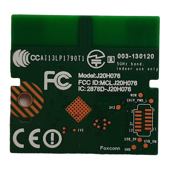
Page 20: Marking Information
Please refer to below for the laser marking details. 1: 2D barcode, content is total 37 digits, include MAC ID, Customer data, and SONY Part Number 2: MAC address 3: Foxconn model name – Label version 4: Foxconn manufacture order 5: SONY Part Number... -
Page 21: Packing Information
11 Packing Information... - Page 23 Federal Communication Commission Interference Statement This device complies with Part 15 of the FCC Rules. Operation is subject to the following two conditions: (1) This device may not cause harmful interference, and (2) this device must accept any interference received, including interference that may cause undesired operation.
- Page 24 This device is intended only for OEM integrators under the following conditions: 1) The antenna must be installed such that 20 cm is maintained between the antenna and users, and 2) The transmitter module may not be co-located with any other transmitter or antenna.
- Page 25 Industry Canada statement: This device complies with RSS-210 of the Industry Canada Rules. Operation is subject to the following two conditions: (1) This device may not cause harmful interference, and (2) this device must accept any interference received, including interference that may cause undesired operation. Ce dispositif est conforme à...
- Page 26 This transmitter module is authorized only for use in device where the antenna may be installed such that 20 cm may be maintained between the antenna and users. The final end product must be labeled in a visible area with the following: “Contains IC: 2878D-J20H076”. Plaque signalétique du produit final Ce module émetteur est autorisé...
- Page 27 Manuel d'information à l'utilisateur final L'intégrateur OEM doit être conscient de ne pas fournir des informations à l'utilisateur final quant à la façon d'installer ou de supprimer ce module RF dans le manuel de l'utilisateur du produit final qui intègre ce module.
- Page 28 sont désignés utilisateurs principaux (c.-à-d., qu’ils ont la priorité) pour les bandes 5 250-5 350 MHz et 5 650-5 850 MHz et que ces radars pourraient causer du brouillage et/ou des dommages aux dispositifs LAN-EL. For Taiwan:低功率電波輻射性電機管理辦法 第十二條 經型式認證合格之低功率射頻電機,非經許可,公司、商號或使用者均不得擅自變更頻率、加大 功率或變更原設計之特性及功能。 第十四條...
Need help?
Do you have a question about the J20H076 and is the answer not in the manual?
Questions and answers