Table of Contents
Advertisement
OPERATION and MAINTENANCE
MANUAL
for
MODEL PV-225208
225 kW Grid-Tied Photovoltaic Inverter
Document #151811
Revision C November 26, 2003
IMPORTANT SAFETY INSTRUCTIONS
SAVE THESE INSTRUCTIONS - THIS MANUAL CONTAINS IMPORTANT INSTRUC-
TIONS FOR XANTREX TECHNOLOGY MODEL PV-225208 GRID TIED PHOTOVOLTAIC
INVERTER THAT SHALL BE FOLLOWED DURING INSTALLATION AND MAINTENANCE
OF THE PV-225208.
Xantrex Technology Inc.
161-G SOUTH VASCO ROAD
Livermore, CA 94550
(925) 245-5400
Copyright 2003, Xantrex Technology Inc.
Advertisement
Table of Contents

Related Manuals for Xantrex PV-225208


Summary of Contents for Xantrex PV-225208
-
Page 1: Operation And Maintenance
Revision C November 26, 2003 IMPORTANT SAFETY INSTRUCTIONS SAVE THESE INSTRUCTIONS - THIS MANUAL CONTAINS IMPORTANT INSTRUC- TIONS FOR XANTREX TECHNOLOGY MODEL PV-225208 GRID TIED PHOTOVOLTAIC INVERTER THAT SHALL BE FOLLOWED DURING INSTALLATION AND MAINTENANCE OF THE PV-225208. Xantrex Technology Inc. -
Page 2: Table Of Contents
Table of Contents Product Description Introduction ... 1-1 Major Components ... 1-1 Control Components ... 1-2 Interconnection Standards Compliance ... 1-3 Specifications ... 1-4 Equipment Symbol ... 1-4 Safety Safety Features ... 2-1 Isolation Procedure ... 2-2 Installation And Initial Turn-On Isolation Transformer Requirements ... -
Page 3: Product Description
IPM (Intelligent Power Module), insulated gate bi-polar transistors (IGBT’s) and gate drive circuits to allow interface of a photovoltaic array with a utility grid. The PV-225208 consists of an inverter bridge, photovoltaic controller, and associated control electronics. The PV-225208 control software provides for complete overall system control with a variety of protection and safety features. -
Page 4: Control Components
DC bus and the utility grid. Operator Interface The operator interface is located on the front door of the PV-225208 main enclosure. It consists of an On/Off switch and a keypad with liquid crystal display for control and monitoring purposes. All interface components are NEMA-3R rated. -
Page 5: Interconnection Standards Compliance
DC power supplies to support its operation. INTERCONNECTION STANDARDS COMPLIANCE The PV-225208 has been tested and listed by Underwriters Laboratories to be in compliance with UL1741 Static Inverters And Charge Controllers For Use In Photovoltaic Power Systems, as well as IEEE- 929-2000 Recommended Practice For Utility Interface Of Photovoltaic (PV) Systems. -
Page 6: Specifications
The PV-225208 has been designed for photovoltaic power systems, which operate within the following speci- fications. Application of the PV-225208 in a manner inconsistent with these specifications may cause damage to the PV-225208 and other system components, and is a violation of the terms of the warranty. a t l... -
Page 7: Safety
PV-225208 and open the A/C contactor within the unit. The A/C contactor cannot be closed unless the switch is in the on position. The PV-225208 is prevented from being restarted until the on/off switch is turned back to the on position. Cycling the on/off switch will reset the PV-225208 and attempt to clear any system fault. -
Page 8: Isolation Procedure
In the event of a utility outage, these adjustments destabilize the feedback between the inverter and the remaining load, resulting in an over/under frequency or voltage condition. The PV-225208 then performs an orderly shutdown. The fault condition will remain until the utility voltage and frequency have returned to normal for 5 minutes. -
Page 9: Installation And Initial Turn-On
INSTALLATION AND INITIAL TURN-ON ISOLATION TRANSFORMER REQUIREMENTS The PV-225208 UL1741 certification requires the use of a Xantrex Technology specified 225 kVA WYE/ WYE isolation transformer between the inverter AC output and the utility interconnection (See Appendix in Section 7 for transformer dimensions and specifications. This custom 225 kVA isolation transformer is not part of the 225 kVA inverter, but can be ordered as a separate item. -
Page 10: Installation Instructions
Technology recommends using 250 MCM, 105 degrees C, minimum, copper wire for all connections to the PV-225208. Ventilation Considerations Maintain a minimum of 12” clearance in back , front and both sides of the PV-225208 for proper cooling fan operation. Installation 1. - Page 11 Cable Entry Area Array Grounding NEC 690-41/42 requires the PV array to be earth grounded. The PV-225208 chassis is also bonded to the PV safety ground terminal block. Refer to the system schematic in the appendix for further wiring configura- tion.
-
Page 12: Interconnection Wiring
@208VAC, or 400 amperes @480VAC maximum branch circuit overcurrent protec- tion in accordance with the National Electrical Code, ANSI/NFPA 70. The following wires for connecting the PV-225208 to external devices are not provided by Xantrex Technolo- gy: (See installation diagram on pages 3-5.) Connect 3-Phase 208 VAC inverter output (AC Disconnect switch) to terminals of the 208 VAC inverter side of isolation transformer. - Page 13 SECTION 3 INSTALLATION AND INITIAL TURN-ON DOCUMENT: 151811 PV-225208 Photovoltaic Inverter Operation and Maintenance Manual Copyright 2003, Xantrex Technology Inc.
-
Page 14: Initial Turn On Procedure
The following must be performed by an approved Technician: The following procedures are intended to verify correct installation and proper operation of the PV-225208. These steps are to be followed sequentially. Do not continue if any of the steps or results are unclear. Refer to Section 4 for a detailed description of system operation. - Page 15 Close the PV-225208 DC disconnect switch. Press <F2> on the operator interface panel. If the PV voltage is above the PV Start Voltage setpoint, the second line should read ‘Waking Up’. Once the PV Start Time is exceeded, the PV-225208 should transition to ‘Power Tracking’.
- Page 16 INSTALLATION AND INITIAL TURN-ON Power Tracker Fine Tuning: All PV-225208 operating parameters have been set at the factory, based upon prior experience with PV arrays. Contact your Xantrex Technology distributor for further information. It is recommended that the PV-225208 be watched during Wake-Up and Sleep Test. If the PV-225208 cycles between operating and sleeping at either of these times, the condition setpoints are not set properly (refer to section 4 for detailed description of PV-225208 state transitions).
-
Page 17: Operation
Fault states are automatic from any state of operation. A fault will cause the PV-225208 to immediately stop processing all power. The fault condition will be reported to the operator interface. The on/off switch, located on the front door of the PV-225208, must be switched to the on position for all operating states. -
Page 18: Operation Features
• The On/Off switch, located on the front door of the PV-225208, must be in the On position for all operating states except Matrix Test, in which case it must be in the Off position. -
Page 19: Operator Interface
Toward the end of every solar day, the PV-225208 automatically determines when to stop producing power dependent upon the output power of the inverter. As the net output power of the PV-225208 nears zero, a timer is started to allow the inverter to ride through any brief irradiance reductions. - Page 20 The ability to adjust the voltage and frequency setpoints with respect to the actual utility voltage and frequency has been provided as a simulation tool to verify the PV-225208 accurately detects and responds to a utility excursion. This test should only be performed by a trained service technician. It is possible to adjust the setpoints in a manner that will prevent the PV-225208 from functioning.
-
Page 21: Manual State Transitions
Press <ENTER>. The LCD will prompt: ‘Press F4 to Confirm’. Press <F4> and the PV-225208 will transition to this goal state. If the goal state requested violates the conditions of the state machine, the PV-225208 will remain in the previous state of operation. -
Page 22: Automatic State Transitions
Power Tracking. If the PV power drops below the PV power stop setpoint (PV P Stop) the PV-225208 will start a PV sleep timer (PV T Stop). If the PV voltage and power remain below their respective setpoints for the... -
Page 23: Auto-Restart Feature
Any State Fault: If the PV-225208 encounters a fault, regardless of operating state, it will transition to the Fault state. The PV-225208 will remain in this state until the fault condition has been remedied and cleared via the front panel. -
Page 24: Troubleshooting
TROUBLESHOOTING GENERAL In the event of a fault, the PV-225208 will annunciate the condition at the operator interface. The PV-225208 will execute an orderly shutdown and remain faulted until the fault is cleared (manually or automatically). In general, the operator should respond to any PV-225208 fault as follows: 1. - Page 25 This fault is self-clearing. Once the utility frequency has recovered within the acceptable operating range, the PV-225208 will automatically clear this fault and resume normal operation after 5 minutes. If the fault will not clear, verify the adjustable setpoint is below the actual utility frequency. If the fault is sustained, contact your Xantrex Technology distributor for assistance or service.
- Page 26 The PCU was not able to service the interrupt for approximately 1 second. Attempt to clear the fault and restart the PV-225208 by pressing the black reset button on the lower left corner of the PCU. If the fault is sustained, replacement or service of the PCU will be necessary.
- Page 27 Make sure the fiber optics for the device and matrix in question are properly connected to the driver board. Similarly, make sure the fiber is properly connected at the PCU. Clear the fault and restart the PV-225208. If the fault is sustained, contact your Xantrex Technology distributor for assistance or service.
- Page 28 SECTION 5 TROUBLESHOOTING Pins 1 and 3 are correct, the CT may be damaged. Clear the fault and restart the PCU. If the fault is sustained contact your Xantrex Technology distributor for assistance or service. 0828 – PV Over-Current Fault (S) Current through the PV CT has exceeded the allowable limit.
-
Page 29: Preventative Maintenance
Call your Xantrex Technology distributor for factory replacements or specifications. Electrical Connections Inspect the condition of all wiring within the PV-225208. Inspect all wire crimps and connections for damage caused from high temperature. Check for corrosion. Replace any damaged wires. Verify all mechanical connections are sufficiently tightened. -
Page 30: Isolation Procedure
5. Turn the on/off switch to the on position. After a 15 second initialization period and a 5 minute wake up period, the PV-225208 will automatically begin power tracking, given the PV voltage is greater than the PV start voltage setpoint. -
Page 31: Appendix
DOCUMENT: 151811 PV-225208 Photovoltaic Inverter Operation and Maintenance Manual s t i s t i Copyright 2003, Xantrex Technology Inc. a t l a t l r e t o l r a i l i x i r... - Page 32 DOCUMENT: 151811 PV-225208 Photovoltaic Inverter Operation and Maintenance Manual s t i s t i C ° Copyright 2003, Xantrex Technology Inc. t l u i t r - n i i t t a t l a t l...
- Page 33 1% off from the actual grid voltage at full load due to the 1% regulation of the isolation transformer. The PV-225208 uses phase to phase voltage measurement to detect the under/over voltage trip limits. For an unbalanced, single phase voltage variation of +10% and -12% as per UL1741 the trip limits must be set to 220V for maximum AC voltage and 193V for minimum AC voltage.
-
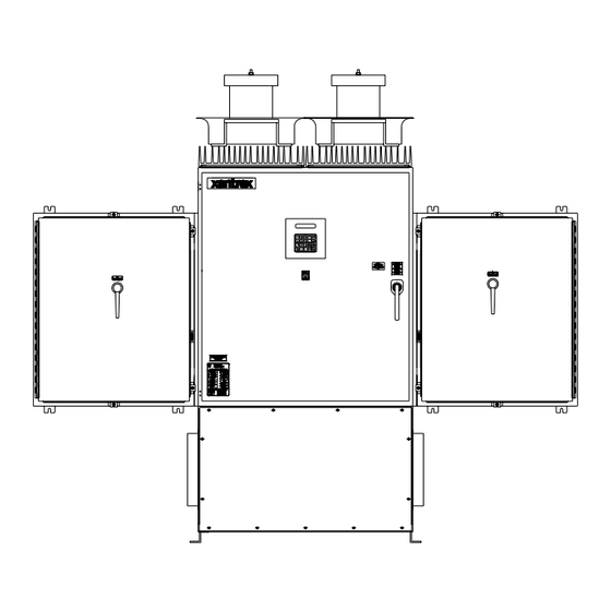
Page 34: Drawings List
Xantrex Inverter Warranty Registration Underwriters Laboratories Compliance Of Standard UL1741 DRAWINGS LIST 151828 : Schematic, System, Grid Tied PV Inverter, PV-225208 151807 : Envelope Drawing, Grid Tied Inverter, PV-225208 151808 : Enclosure, Main, Control Components, PV-225208 151809 : Enclosure, AC Interface, PV-225208... - Page 35 XANTREX PV SERIES LIMITED WARRANTY AND REGISTRATION Xantrex Technology warrants all equipment supplied to Customer under this purchase order against defects in workmanship and material for a period of (12) twelve months from delivery, provided that the equipment has been operated and maintained in accordance with the service manual provided with the equipment.
- Page 41 Assembly Description: Main Enclosure, Control Components, PV-225208 Xantrex Technology Assembly # 151808 Item # Reference Designator T3,T4,T5 SSR1,SSR2 C4,C5 CT1,2,3,4,5,6,8 B1,B2 TB2,TB3 F4-12 F13,14 F7,8 F9-12 F4-6,13,14 L1,L2 B4,B5 TS1,TS2 Reference Designator 151808 Xantrex Technology Inc. PV-225208 Photovoltaic Inverter Major Parts List...
- Page 43 Assembly Description: Enclosure, AC Interface, PV-225208 Xantrex Technology Assembly # 151809 Item # Reference Designator F1-3 F1-3 151809 Xantrex Technology Inc. PV-225208 Photovoltaic Inverter Major Parts List Xantrex Technology Part # 1-151784-01 Fab, Enclosure, DC Interface, PV225208 1-151754-01 Fab, Panel, Encl, AC, PV225208...
- Page 45 Assembly Description: Enclosure, DC Interface, PV-225208 Xantrex Technology Assembly # 151810 Item # Reference Designator 151810 Xantrex Technology Inc. PV-225208 Photovoltaic Inverter Major Parts List Xantrex Technology Part # 1-151783-01 Fab, Enclosure, DC Interface, PV225208 1-151755-01 Fab, Panel, Encl, DC, PV225208...
- Page 46 XFMR, 225KVA, 3 PHASE, 60Hz, 208Y MANUFACTURER SQUARE D MFG’S PART NO. 208Y208 225TQ56373 (Custom Built) 208Y480 225TQ56374 (Custom Built) DATA SOURCE: http://www.squared.com/ Xantrex Technology Inc. 161-G South Vasco Road Livermore, CA, USA 94550 DATE DRAWN 1321 12/9/2002 XANTREX PART NO. 1-151812-01 1-151812-02 Q.C.
Need help?
Do you have a question about the PV-225208 and is the answer not in the manual?
Questions and answers