Advertisement
WARNINGS AND CAUTIONS
• Read and understand all instructions. Follow all warnings and instructions marked on the product.
• Do not use this product near water - e.g., near a tub, wash basin, kitchen sink or laundry tub, in a
wet basement, or near a swimming pool.
• Never push objects of any kind into this product through openings, as they may touch dangerous
voltages.
• SAVE THESE INSTRUCTIONS.
SPECIFICATIONS
Dimensions:
2.75W x 2.75H x 1D
Temperature Range:
-40
o
F - 120
Humidity Range:
0% - 100% relative humidity
Current Consumption: 15mA maximum
DESCRIPTION
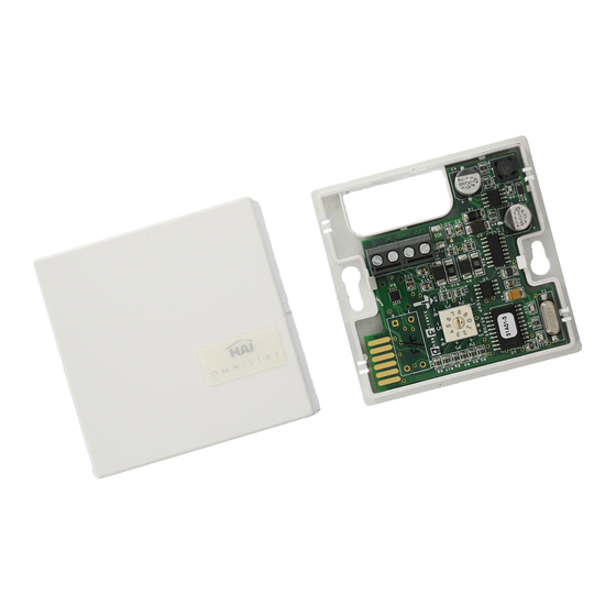
The Model 31A00-8 Extended Range Temperature and Humidity Sensor is used for sensing temperatures from -40
Firmware Version 2.8 or higher. It can also be used for reporting the relative humidity from 0 to 100 percent. The Model 31A00-8 features a new, high accuracy temperature sensor.
The temperature can be used to activate programs for controlling temperatures in attics, garages, greenhouses, basements, wine cellars, coolers, and freezers. The temperature
can be displayed on the console or touchscreen, or spoken over the telephone. It can also report, log, alert, or generate an alarm if the temperature reaches freeze conditions or if
the temperature goes above the high setpoint or drops below the low setpoint programmed in the system.
High and low humidity limits can be set for taking action (i.e. turning on the bathroom vent fan, running a/c in de-humidification mode, turning on humidifier in heating mode, etc.)
or reporting high or low humidity conditions in homes, greenhouses, wine cellars, coolers, humidors, etc. Controlling humidity is particularly helpful in combating the growth of
mold in vulnerable areas of the home, such as bathrooms, basements, attics, etc.
When used outdoors, the Model 31A00-8 should be mounted under an overhang to protect it from direct sunlight and rain. It is coated with a sealant to withstand outdoor
moisture. The outdoor temperature and/or humidity can be displayed on the console or touchscreen, or spoken over the telephone. Furthermore, the outdoor temperature can be
displayed on a Leviton communicating thermostat. Automation programs, macros, and indoor appliances can be controlled based on the outdoor temperature and/or humidity.
INSTALLATION
1. Each Model 31A00-8 requires one zone input on the Leviton controller or Expander Module for temperature. The Model 31A00-8 can not be connected to a zone on an
Expansion Enclosure (i.e. Model 17A00) for temperature. It also requires one zone input for humidity. Run a 4-conductor wire from the controller location to each Model 31A00-
8. The humidity sensor can be used without using the temperature sensor.
2. Mount the Model 31A00-8 using the supplied wall anchors, screws, and mounting bracket (if desired). For optimal temperature and humidity readings, mount it vertically so
that the white arrow (silk-screened onto the board) points upward as shown in FIGURE 1. The plastic enclosure must be mounted so that the airflow slots are at the top and
bottom. Connect to controller as shown in FIGURE 1.
3. Program the zone type for the temperature output (T) as an "Extended Range" device: ER Outdoor Temperature (Type 85), ER Temperature (Type 86), or Temperature Alarm
(Type 87) based on the application.
4. Program the zone type for the humidity output (H) as Humidity (Type 84).
CALIBRATION
The temperature sensor in the Model 31A00-8 is shipped from the factory adjusted to its optimal setting. If however, the temperature reading seems to differ from the ambient
temperature, you may adjust the output of the Model 31A00-8 to compensate for the difference. The current temperature output may be raised between 1
between 1
F and 5
F.
o
o
To make an adjustment, use the rotary switch labeled "Temp Adjust". Place a small screwdriver in the slot on the rotary switch and turn it to the appropriate setting 0-9.
By default, the rotary switch is set to "0" which means no change. A setting from 1-4 will adjust the current temperature by +1
adjust the current temperature by -5
TEMPERATURE AND HUMIDITY SENSOR
Installation Instructions
o
F
F through -1
F, respectively.
o
o
FIGURE 1 – MODEL 31A00-8 CONNECTIONS
BLACK
RED
EXTENDED RANGE
Cat. No. 31A00-8
INSTALLATION
WARNINGS AND CAUTIONS
• Never install communications wiring or components during a lightning storm.
• Never install communications components in wet locations unless the
components are designed specifically for use in wet locations.
• Never touch uninsulated wires or terminals unless the wiring has been
disconnected at the network interface.
• Use caution when installing or modifying communications wiring or
components.
YELLOW
GREEN
RED
BLACK
GREEN
YELLOW
F - 120
F when connected to an Leviton Home Control System with
o
o
F through +4
F, respectively. A setting from 5-9 will
o
o
TEMP ADJUST
-1 0
+1
0
-2
+2
-3
+3
-4
-5
+4
DI-021-EM318-00A
(31I00-8)
ENGLISH
F and 4
F or lowered
o
o
Advertisement
Table of Contents

Summary of Contents for Leviton 31A00-8
- Page 1 F when connected to an Leviton Home Control System with Firmware Version 2.8 or higher. It can also be used for reporting the relative humidity from 0 to 100 percent. The Model 31A00-8 features a new, high accuracy temperature sensor.
- Page 2 Leviton’s option, of Product that fails due to defect in material or workmanship. Leviton reserves the right to replace product under this Limited Warranty with new or remanufactured product. Leviton will not be responsible for labor costs of removal or reinstallation of Product. The repaired or replaced product is then warranted under the terms of this Limited Warranty for the remainder of the Limited Warranty time period or ninety (90) days, whichever is longer.


Need help?
Do you have a question about the 31A00-8 and is the answer not in the manual?
Questions and answers