Table of Contents

Related Manuals for Unitech PT600


Summary of Contents for Unitech PT600
- Page 1 USER’S GUIDE PORTABLE DATA COLLECTION TERMINAL PT600 DOCUMENT NUMBER: 350600-0010...
- Page 2 NOTICE The unit is equipped with a NiMH battery pack, however it may not be powered on due to discharging of the battery by putting in storage for a period of time. In the case of above situation happened, plug in an 9V AC-DC adapter and recharge the NiMH battery pack about 14~16 hours or put into cradle about 2.5 hours...
-
Page 3: Table Of Contents
Table of Content Chapter 1 Introduction ... Technical Specification ... 2 Interface Ports ... 8 Using the Keyboard ... 9 Triggering Scanner Module... 11 Application Development Environment ... 12 Optional Charging/Communication Cradle... 13 Chapter 2 Power System... Power Supply...14 Power Low Indication...14 Battery Replacement ...15 Recharging the Battery Pack ...17 Storage and Safety Precautions ...18... -
Page 4: Chapter 1 Introduction
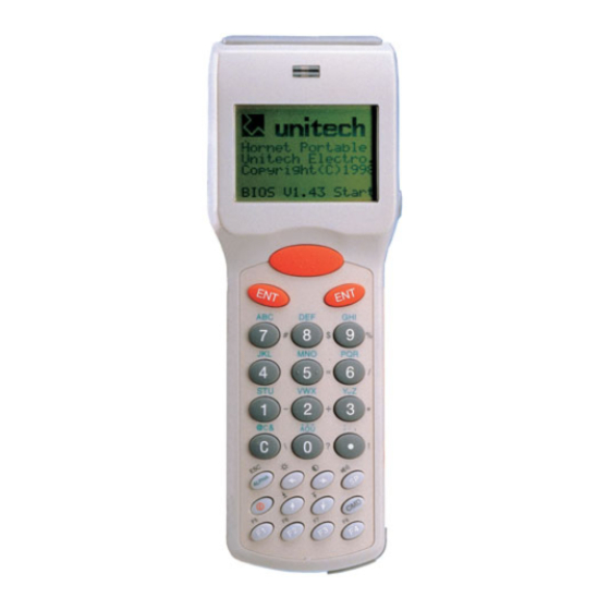
Chapter 1 Introduction The PT600 Portable Data Terminal, referred as PDT hereafter, with integrated laser scanner or pen scanner is a rugged, compact and lightweight hand-held data collection terminal with good reliability, flexibility and maintainability. Its compact size and form makes it even fits in your packet. -
Page 5: Technical Specification
Technical Specification SOFTWARE PROGRAMMING TOOLS Language Assembly, C language (MSC, Turbo C, Visual C) JobGen Plus A Windows-based transaction program generator JobGen Pro A Dos-based transaction program generator FormCaching A built-in program generator CPU/MEMORY 16-bit 8088 compatible microprocessor CPU Memory 512KB to up of 4.5MB SRAM Flash ROM 256K with DOS-based system... - Page 6 Power input AC/DC adapter @ 9VDC/500mA DOCKING STATION Interface One serial infrared interface for data communication via PT600 One RS485 port for RS485 multiple stations networking One RS232 port for point-to-point communication to host computer Power charging Soft-contact charging pads to main unit and spare battery Quick charging for typical 2.5 hours...
- Page 7 Built-in power-on self test and diagnostic program Host command remote control Integrated Laser Diode Scanner Scan rate Skew Tolerance Pitch Angle Power consumption 60mA typ.@5V Integrated clip-on Pen Scanner Resolution Dept of field Scan rate Reading Angle Print Contrast Ratio 0.5 min Diagram shown with a Built-in Integrated Laser scanner Skew Tolerance Scan Beam...
- Page 8 Depth of Field diagram - 5 -...
- Page 9 - 6 -...
- Page 10 Diagram shown with a clip-on pen scanner 45° 45° - 7 -...
-
Page 11: Interface Ports
Interface Ports The PT600 has a RS232C serial port with miniature RJ10 connector, Communication by Infrared LED which on the left side of lower cabinet and charging pads locate on the bottom. Pin Signal Direction Description DC9 V Input External... -
Page 12: Using The Keyboard
Using the Keyboard The keypad of PT600 consists of 27 rubber keys, the switch on/off the unit and other 26 keys are used to control the unit and key in data. The use of keyboard is categorized to three modes: normal mode, command mode, and alpha(betic) mode. -
Page 13: Normal Mode
NORMAL mode Keyboard of the PT600 is initialized to normal mode after powered on. In normal mode, the cursor is a block sign and the keyboard is mainly used to input numeric data and use F1-F4 four function-keys. The keypad layout of available keys in normal mode is shown on right picture. -
Page 14: Triggering Scanner Module
To enter ‘C’, hit [è] then [7]. Triggering Scanner Module The PT600 can be used with a built-in integrated laser scanner module or clip-on pen scanner module. The built-in decoder reads barcode labels of all major bar code labels. The user should keep laser window or tip of pen clean to prevent low reading rate of distorted bar code input signal. -
Page 15: Application Development Environment
JobGen Pro to the PT600. After data collected and processed on the PT600, the data can be uploaded to the PC for further processing. -
Page 16: Optional Charging/Communication Cradle
Optional Charging/Communication Cradle An optional charging/communication cradle (docking station), PT016, gives users a convenient accessory for daily use of the PT600. The cradle has been incorporated a quick charge circuit that the NiMH battery pack installed in the unit along with an extra spare pack can be fully charged in about 2.5 hours. -
Page 17: Chapter 2 Power System
RTC (real time clock chip) and RAM memory to provide users a data-loss free environment. Normally the PT600 gets power from main power source to back-up RTC and RAM and puts the Lithium battery in standby state. When the main... -
Page 18: Battery Replacement
When the main battery low condition occurs, the main battery can continue to supply power for about 10 ~ 30 minutes, however the unit may reach the system power cutoff point and automatically turn itself off. Meanwhile the unit continues to back-up the data contents in RTC and RAM, but it cannot be powered up until the batteries have been recharged or replaced. - Page 19 Remove battery pack Remove backup battery Lithium Back up Battery 1. Refer to the procedure in previous paragraph, un-screw the backup battery cover and as illustration above to remove the lithium battery. 2. Insert a new battery into the holder with correct orientation. 3.
-
Page 20: Recharging The Battery Pack
Recharging the Battery Pack When the PDT shows “Main battery low” message or sign , the battery pack in PDT needs to be recharged. There are two ways to charge the battery: regular and quick charging as shown below. Regular Charging AC to 9V DC Transformer Plug one end of an AC-9VDC power adapter into the DC-jack of RS232... -
Page 21: Storage And Safety Precautions
Charging Considerations It is important to consider the surrounding temperature whenever you are charging the NiMH battery pack. The process is most efficient at normal room temperature or slightly cooler. It is essential that you charge batteries within the stated range of 32 F to 113 F (0 C to 45 C). Charging batteries outside of the specified range could damage the batteries and shorten their life cycle. -
Page 22: Chapter 3 Operation
Supervisor mode is also protected with password checking to prevent unauthorized personnel from changing the system configuration. (for PT600 detail information please refer to PT600 Technical Binder) Ready Mode The PDT performs a Power-On-Test and Warm-Start when it is switched on. -
Page 23: 3.2 User Mode And System Commands
Ready mode prompt The first line indicates the model code and version number (e.g. V1.00). The second line shows the PT600 Vx.xx size of the total installed RAM (i.e. 4608 KB). MEM 4608 KB The third line prompts a ">" which indicates that >... - Page 24 from a Host computer. In this mode, data input from bar code reader or keyboard is displayed on screen and output to RS-232 port. Data received from the serial port is displayed on the LCD screen. Communication parameters, such as baud rate, data bits, parity, stop bits and flow control, must be set to be compatible with the destination in order to send data properly.
-
Page 25: Configure The Terminal In Set Command
This command dumps the content of a file on the PDT's LCD. The content of the file will be displayed 128 (16 character x 8 line) characters at a time. Press any key to show the next page or hit [CMD] then [ALPHA] keys to return to User mode prompt. - Page 26 [ENT] to confirm. SCANNER Enable / disable bar code decoding. PEN SCAN KEY When pen scanner is used on PT600, user can setup whether pressing trigger key to enable pen scanner. If ENABLE is selected, user must press and hold down trigger to scan barcode label.
-
Page 27: Upload/Download By Esc Command
PDT can also be instructed to process the data communication by remote ESC commands through built-in MULTI communication protocol.(please refer to PT600 Technical Binder for detail information) After linking the PDT to a PC/host through RS232 interface a... -
Page 28: Chapter 4 Built-In Application:formcaching
Chapter 4 Built-in Application: FormCaching The system of PDT includes a built-in application, FormCaching, that allows user to create a data entry application by specifying field prompt, type, length, input method and delimiter,...,etc. without writing program and loading to the terminal. 4.1 Specification of FormCaching DATA FIELD DEFINITION: maximum field number=8 Category... -
Page 29: How To Create A Formcaching
You will need to enter Supervisor mode and select “4.FORM” category in order to set the configuration of FormCaching (refer to the PT600 Programming Reference Manual for how to enter the Supervisor mode). After selecting the “4.FORM” in Supervisor mode, the screen will show as above. -
Page 30: Default Settings Of Formcaching
After collecting data, the FORM.DAT file can be uploaded to host either by invoking kermit server in User mode described in section 3.2 or remote ESC command described in 3.4. Default Setting of FormCaching In default, the FormCaching is initialized with settings as shown in the table below. - Page 31 Warning This is a Class A product in a domestic environment this product may cause radio interference in which case the user may be required to take adequate measures. - 28 -...
Need help?
Do you have a question about the PT600 and is the answer not in the manual?
Questions and answers