
Related Manuals for KEP SUPERtrol-1LE


Summary of Contents for KEP SUPERtrol-1LE
- Page 1 SUPERtrol-I LE omputer Version 4.X KESSLER-ELLIS PRODUCTS 10 Industrial Way East Eatontown, NJ 07724 800-631-2165 • 732-649-7100 Fax: 732-649-7099 99572 01/31/17...
- Page 2 Proprietary Notice The information contained in this publication is derived in part from proprietary and patent data. This information has been prepared for the expressed purpose of assisting operating and maintenance personnel in the efficient use of the instrument described herein. Publication of this information does not convey any rights to use or reproduce it or to use for any purpose other than in connection with the installation, operation and maintenance of the equipment described herein.
-
Page 3: Table Of Contents
CONTENTS 1. DESCRIPTION 1.1 Unit Description ..........................1 1.2 Unit Features..........................1 1.3 Specifications ..........................2 2. INSTALLATION 2.1 General Mounting Hints ....................... 6 2.2 Mounting Diagrams ........................6 3. APPLICATIONS 3.1 Liquid Volume..........................7 3.2 Batching ............................8 4. WIRING 4.1 Typical Batcher Wiring ......................... - Page 4 CONTENTS 7. PRINCIPLE OF OPERATION 7.1 General ............................33 7.2 Flow Equations........................... 33 7.3 Linearization Table ........................34 7.6.1 Linearization Table General Information ..............34 7.6.2 Linearization Table for Pulse Inputs ................34 7.6.3 Linearization Table Interpolation ................34 8. TEST, SERVICE and MAINTENANCE 8.1 Test Menus ..........................
-
Page 5: Description
SUPERtrol-I LE Flow Computer 1. Description 1.1 Unit Description: The ST1LE Flow Computer satisfies the rate, total and batching instrument requirements for a variety of pulse producing flowmeter types in liquid applications. Multiple flow equations and instrument functions are available in a single unit with many advanced features. The alphanumeric display shows measured and calculated parameters in easy to understand format. -
Page 6: Specifications
SUPERtrol-I LE Flow Computer 1.3 Specifications: Power Input The factory equipped power option is internally fused. An internal line to line filter capacitor is provided for Specifications: added transient suppression. Environmental Order Option 1: 110VAC: 85 to 127 Vrms, 50/60 Hz Indoor Use Order Option 2: 220VAC: 170 to 276 Vrms, 50/60 Hz Altitude up to 2000m... - Page 7 SUPERtrol-I LE Flow Computer Excitation Voltage Analog Output The analog output is menu assignable to correspond 110/220 VAC Powered Units to the Rate or Total. Menu Selectable: 5, 12 or 24 VDC @ 100mA Type: Isolated Current Sourcing 24 VDC Powered Units Isolated I/P/C: 500 V Menu Selectable: 5 or 12 VDC @ 100mA Available Ranges:...
- Page 8 SUPERtrol-I LE Flow Computer Operating Mode Setup Mode The Flow Computer can be thought of as making The setup mode is password protected by means a measurement of flow and then performing of a numeric lock out code established by the user. calculations which are then updated periodically In addition, a secret, manufacturers numeric unlock on the display as rate and total.
- Page 9 SUPERtrol-I LE Flow Computer Maintenance (Test) Mode: Operation of Serial Communication Port with Printers The Maintenance Mode of the ST1LE provides a number of specialized utilities required for instrument ST1LE's RS-232 channel supports a number of checkout on start-up, setup documentation and data operating modes.
-
Page 10: Installation
SUPERtrol-I LE Flow Computer 2. Installation 2.1 General Mounting Hints: The ST1LE Flow Computer should be located in an area with a clean, dry atmosphere which is relatively free of shock and vibration. The unit is installed in a 5.43" (138mm) wide by 2.68" (68mm) high panel cutout. -
Page 11: Applications
SUPERtrol-I LE Flow Computer 3. Applications 3.1 Liquid Volume Measurements: A flowmeter measures the actual volume in a liquid line. Calculations: • For Flowmeters with Pulse Outputs, Volume flow is calculated using the flowmeter frequency output and the user entered K-Factor or Linearization Table. Output Results: •... -
Page 12: Batching
SUPERtrol-I LE Flow Computer 3.2 Batching Measurements: A flowmeter measures the actual volume in a liquid line. Calculations: • For Flowmeters with Pulse Outputs, Volume flow is calculated using the flowmeter frequency output and the user entered K-Factor or Linearization Table. Output Results: •... -
Page 13: Wiring
SUPERtrol-I LE Flow Computer 4 WIRING 4.1 Typical Batcher Wiring: (+) V DC OUTPUT FLOW Signal PULSE IN 1 PULSE IN 2 Common COMMON NOT USED FLOW METER NOT USED with Pre Amp NOT USED NOT USED Stop Start CNTR IN 1 CNTR IN 2 SEE USER MANUAL... -
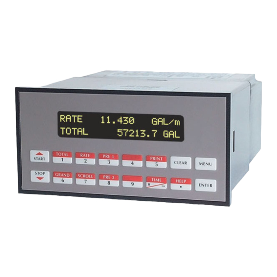
Page 14: Unit Operation
SUPERtrol-I LE Flow Computer 5. UNIT OPERATION 5.1 Front Panel Operation Concept for Run Mode The ST1LE is fully programmable through the front panel. Please review the following usage summary TOTAL RATE PRE 1 CLEAR MENU START before attempting to use the instrument. GRAND SCROLL PRE 2... -
Page 15: General Operation
SUPERtrol-I LE Flow Computer 5.2 General Operation The unit can display: Rate, Total, Grand Total, Presets and Time of Day. The unit can be programmed to perform Ratemeter/Totalizer or Batching functions. 5.3 Ratemeter/Totalizer Operation The Ratemeter/Totalizer mode is used primarily to monitor flowrate and accumulated total. The relays can be used to trigger on flow rate, total, or alarms. -
Page 16: Rs-232 Serial Port Operation In Rate/Total Mode
SUPERtrol-I LE Flow Computer 5.3.5 RS-232 Serial Port Operation in Rate/Total mode The RS-232 serial port can be used for programming (using the Setup Disk) or for communicating to printers and computers in the Operating Mode (Run Mode). PC Communications: The Setup Disk also allows the user to query the unit for operating status such as Flow Rate, Flow Total, Presets, etc. -
Page 17: Batcher Operation
SUPERtrol-I LE Flow Computer 5.4 Batcher Operation The Batcher mode is used primarily to control batches. The main difference between the Batch mode and Rate/Total mode is the relay operation. The Batch mode allows the operator to "START" the unit via the front panel or remote input. -
Page 18: Password Protection For Batcher Mode
SUPERtrol-I LE Flow Computer START, RESET/START and STOP, STOP/RESET When configuring the control inputs, Control Input1 can be set for START or RESET/START. When set for START, the unit will start batching when a signal is applied to Control Input 1 or the front panel Start key is pressed. -
Page 19: Rs-232 Serial Port Operation In Batcher Mode
SUPERtrol-I LE Flow Computer 5.4.6 RS-232 Serial Port Operation in Batcher mode The RS-232 serial port can be used for programming (using the Setup Disk) or for communicating to printers and computers in the Operating Mode (Run Mode). PC Communications: The Setup Disk also allows the user to query the unit for operating status such as Flow Rate, Flow Total, Presets, etc. -
Page 20: Programming
SUPERtrol-I LE Flow Computer 6. PROGRAMMING 6.1 Front Panel Operation Concept for Program Mode The ST1LE is fully programmable through the front panel. Please review the following usage sum- mary before attempting to use the instrument. TOTAL RATE PRE 1 CLEAR MENU START... -
Page 21: Ez Setup
SUPERtrol-I LE Flow Computer 6.2 EZ Setup The EZ Setup routine is a quick and easy way to configure the unit for the most commonly used instrument functions. This setup assumes that you are measuring Volumetric Flow using a high level, DC Pulsing flow sensor. -
Page 22: Setup Menus
SUPERtrol-I LE Flow Computer 6.3 Setup Menus Display Notes Sub-menus 6.3.1 Select Setup to enter the instrument setup routine. SELECT OPERATE STATE Top Level Setup Menu Setup Test 6.3.2 Refer to Page 17 for Details. STOP SELECT EZ SETUP START Sub-menu Groups STOP... -
Page 23: Setup Sub-Menus
SUPERtrol-I LE Flow Computer 6.4 Setup Sub-Menus Sub-menus Display Notes 6.4.1 Refer to page 17 for EZ Setup routine. SELECT EZ SETUP SELECT EZ SETUP Press the DOWN (stop) key to advance to Instrument STOP Type. Press the UP (start) key to advance to START Administrative Setup. - Page 24 SUPERtrol-I LE Flow Computer Sub-menus Notes 6.4.2 Enter the maximum allowable Batch Preset. The operator MAXIMUM BATCH PRESET will not be able to enter a batch preset larger than this INSTRUMENT TYPE 1000.0 gal value. (continued) STOP START STOP START Select ON to set the unit to operate using a Batch See Section 5.4, see also BATCH OVERRUN COMP...
-
Page 25: Setup Indicators (Total)
SUPERtrol-I LE Flow Computer Sub-menus Display Notes 6.4.3 Press ENTER to begin setup of the Indicators SETUP INDICATORS SETUP INDICATORS (Total) Press ENTER when Total is flashing to configure the SETUP INDICATORS Totalizer Indicators Total Rate Enter the desired Total Descriptor text TOTAL DESCRIPTOR TOTAL Enter the desired Volume Units Label text for the... -
Page 26: Setup Flow Input (Pulse - Cha & Cha=Chb)
SUPERtrol-I LE Flow Computer Sub-menus Display Notes 6.4.5 Press ENTER to begin setup of Flow Input. SETUP FLOW INPUT SETUP FLOW INPUT (Pulse - chA & Select the desired Excitation Voltage for your flow EXCITATION VOLTAGE chA=chB) sensor. Caution: Improper selection may cause damage to sensor NOTE: Enter the desired Pulse type. -
Page 27: Setup Flow Input (Pulse - Quadrature, Qx1 Or Qx2)
SUPERtrol-I LE Flow Computer Sub-menus Display Notes Press ENTER to begin setup of Flow Input. 6.4.6 SETUP FLOW INPUT SETUP FLOW INPUT (Pulse - Quadrature, Select the desired Excitation Voltage. EXCITATION VOLTAGE Qx1 or Qx2) Press ENTER when Pulse is flashing to configure the FLOW INPUT TYPE flow input for Pulse signals. -
Page 28: Setup Pulse Output
SUPERtrol-I LE Flow Computer Sub-menus Display Notes 6.4.7 Press ENTER at this prompt to setup the Pulse Output. SETUP PULSE OUTPUT SETUP PULSE OUTPUT Select the desired Pulse Output Usage. PULSE OUTPUT USAGE Volume Select the desired Pulse Width for the Pulse Output. PULSE WIDTH 10mS 100mS... -
Page 29: Setup Relays
SUPERtrol-I LE Flow Computer Sub-menus Display Notes 6.4.9 Select the desired Relay for setup. SETUP RELAYS (Relays 3 & 4 Optional, menus will always appear even if SETUP RELAYS Rly1 Rly2 Rly3 Rly4 option not installed) (Relay 1 & Relay 2) If Relay 1 or Relay 2 Selected, RELAY 1 USAGE... - Page 30 SUPERtrol-I LE Flow Computer Sub-menus Display Notes 6.4.9 (Continued) Select the desired Relay for setup. SETUP RELAYS (Relays 3 & 4 Optional) SETUP RELAYS Rly3 Rly4 Rly1 Rly2 (Relay 3 & Relay 4) If Instrument Type is set for BATCHER, RELAY 3 USAGE Choose Rate, Total, Alrm, Ovr or NA.
-
Page 31: Setup Control Inputs (Rate/Total)
SUPERtrol-I LE Flow Computer Sub-menus Display Notes 6.4.10 Press Enter to begin setup of the Control Inputs. SETUP CONTROL INPUTS SETUP CONTROL INPUTS (RATE/TOTAL) Select the desired Control Input for setup. SETUP CONTROL INPUTS Input1 Input2 Input3 If Control Input 1 Selected, CONTROL INPUT1 USAGE Select Inhibit Total or NA (Not Assigned). -
Page 32: Setup Realtime Clock (Time)
SUPERtrol-I LE Flow Computer Sub-menus Display Notes 6.4.12 Press Enter to begin setup of the Realtime Clock. SETUP REALTIME CLOCK SETUP REALTIME CLOCK (Time) Select Time to set the time. SETUP REALTIME CLOCK Time Date Select 24Hr or 12Hr clock CLOCK TYPE 24HR 12HR... -
Page 33: Serial Usage
SUPERtrol-I LE Flow Computer Sub-menus Display Notes 6.4.14 Press Enter to begin setup of the Serial Port. SERIAL USAGE SERIAL USAGE Select Serial Hardware type for standard port. RS-232 SERIAL HARDWARE is standard. (See SETUP NETWORK CARD for RS485 RS232 RS485 Modbus option) Select the Device ID (0-99). - Page 34 SUPERtrol-I LE Flow Computer Sub-menus Display Notes 6.4.15 Press Enter to setup the Datalog/Print information. SETUP DATALOG/PRINT SETUP DATALOG/PRINT (Configure) Select Config to configure the Datalog/Print information. SETUP DATALOG/PRINT Config Select_list Select the type of Output Format. OUTPUT FORMAT Printer Term Dbase Enter the desired Page Length.
-
Page 35: Set Datalog/Print (Configure)
SUPERtrol-I LE Flow Computer Sub-menus Display Notes 6.4.16 Press enter to begin Setup Datalog/Print routine. SET DATALOG/PRINT SETUP DATALOG/PRINT (Select_list) Press enter when Select_list is selected to setup print list. SET DATALOG/PRINT Select_list Config PRINT LIST ITEMS TOTAL Use Up and Down arrow keys to view list status. Press the PRINT key to add or remove items from the list. -
Page 36: Setup Network Card
SUPERtrol-I LE Flow Computer Sub-menus Display Notes 6.4.18 Press Enter to setup Network Card. SETUP NETWORK CARD SETUP NETWORK CARD (optional) Select desired Network Protocol. (only Modbus RTU is SELECT NETW PROTOCOL supported) NETWORK DEVICE ID Enter the device address on network (00-247). Select the desired Baud Rate. -
Page 37: Principle Of Operation
SUPERtrol-I LE Flow Computer 7. Principals Of Operation 7.1 General: The ST1LE Flow Computer uses several internal calculations to compute the input frequency based on specific data input. Several computations are performed to yield flow or linearized flow. 7.2 Flow Equations: Uncompensated Flow Computation: Pulse Input;... -
Page 38: Linearization Table
SUPERtrol-I LE Flow Computer 7.3 Linearization Table 7.3.1 Linearization Table General Information The Linearization Table is used when the flow input device gives a nonlinear input signal. The unit uses up to 16 different points, as entered by the operator, to form a curve for linearizing the input signal. -
Page 39: Test, Service And Maintenance
SUPERtrol-I LE Flow Computer 8. Test, Service and Maintenance 8.1 Test Menus Sub-menus Display Notes 8.1.1 Select Test to enter the instrument test & calibration routine. TOP LEVEL SELECT OPERATE STATE NOTE: Supervisor (Service) password required to gain TEST MENUS Test Setup access to this mode. -
Page 40: Test Sub-Menus
SUPERtrol-I LE Flow Computer 8.2 Test Sub-Menus Sub-menus Display Notes 8.2.1 Press Enter to view the audit trail information. Audit Trail Audit Trail Sub-menu Group The configuration audit trail format: Config_Audit nnnnn nnnnn= number of critical menu changes, hh:mm:ss mm/dd/yy hh:mm:ss;... -
Page 41: Keypad Test
SUPERtrol-I LE Flow Computer Sub-menus Display Notes 8.2.4 Press Enter to enter keypad test. Keypad test Keypad test Sub-menu Group Press the various keys and the display will show the key Keypad test that was pressed. Press Menu to exit the test. Key pressed—>... -
Page 42: Pulse Input Test
SUPERtrol-I LE Flow Computer Sub-menus Display Notes 8.2.8 Press Enter key to test the pulse input. Pulse input test Pulse input test Sub-menu Group 2.5V Use the Up/Down arrow keys to select the appropriate Pulse input test STOP 10mV START trigger level. -
Page 43: Excitation Out Test
SUPERtrol-I LE Flow Computer 8.2.11 Press Enter key to test the pulse output. Pulse out test Pulse out test To simulate a frequency on the pulse output: Connect a Sub-menu Group frequency counter to (+)TB1-13, (-)TB1-14. Press the key under the desired frequency Pulse out test setting to move the asterisk (*). -
Page 44: Internal Fuse Replacement
SUPERtrol-I LE Flow Computer 8.3 Internal Fuse Replacement Instructions: 1. Make sure you follow proper E.S.D. Precautions. All persons performing this replacement must follow proper grounding procedures. 2. Turn the power to the unit off. 3. Disconnect the two piece connector rear terminal block, leaving all connections in place. 4. -
Page 45: Rs-232 Serial Port
SUPERtrol-I LE Flow Computer 9. RS-232 Serial Port 9.1 RS-232 Port Description: The ST1LE has a general purpose RS-232 Port which may be used for any one of the following purposes: Transaction Printing Data Logging Remote Metering by Modem (optional) Computer Communication Link Configuration by Computer Print System Setup... -
Page 46: Rs-485 Serial Port
SUPERtrol-I LE Flow Computer 10. RS-485 Serial Port (optional) 10.1 RS-485 Port Description: The ST1LE has a an optional general purpose RS-485 Port which may be used for any one of the following purposes: Accessing Process Parameters Rate, Temperatures, Density, Setpoints, Month, Day, Year, Hour, Minutes, Seconds, etc. Accessing System Alarms System, Process, Self Test, Service Test Errors Accessing Totalizers... -
Page 47: Flow Computer Setup Software
SUPERtrol-I LE Flow Computer 11. Flow Computer Setup Software The ST1LE setup program provides for configuring, monitoring and controlling a ST1LE unit. Sample applications are stored in disk files. The setup program calls these Templates. You can store the setup from the program’s memory to either the ST1LE (Downloading the file) or to a disk file (Saving the file) for later usage. -
Page 48: Using The Flow Computer Setup Software
SUPERtrol-I LE Flow Computer 11.4 Using the Flow Computer Setup Software The setup software window consists of several menu “Tabs”. Each tab is organized into groups containing various configuration and/or monitoring functions. To view the tab windows, simply click on the tab. The previous tab window will be hidden as the new tab window is brought to the foreground. -
Page 49: View Tab
SUPERtrol-I LE Flow Computer 11.7 View Tab The View Tab screen allows for viewing selected group items on the PC in a similar format as shown on the unit display. Data from the following groups can be viewed in the List of Values section: Process Parameters (i.e. -
Page 50: Glossary Of Terms
SUPERtrol-I LE Flow Computer 12. Glossary Of Terms Acknowledge & Clear Alarms Acknowledge is used to clear alarm relays and remove any visual alarm messages from the display. In the run mode, press the ENTER key or activate CONTROL INPUT 3 (if set for ACK) to momentarily clear alarms and alarm messages. Alarms will reassert themselves if alarm conditions are still present. Analog Output The analog signal (4-20mA) that is generated by the ST1LE. It can correspond to the Rate or Total. This output is used primarily for transmission of process information to remote systems. Audit Trail The audit trail is used to track the number of changes made to the units setup program and calibration. Auto Batch Restart The Auto Batch Restart function allows the user to set an amount of time to automatically restart a batch after the completion of a batch. This time can be set from 1 to 99 seconds. Batch Count Mode Batch Count Mode specifies the user preference for count direction. The "Up" selection begins with a value of "0" and counts up until the batch size is reached. The "Down" selection begins with a value equal to the desired batch size and counts down to "0". Batch Overrun The ST1LE offers a batch overrun compensation routine. If batch overrun occurs due to slow valve response time, the unit will compensate for the overrun amount on the next batch. This feature can be disabled if desired. NOTE: A nonzero MAX DRAIN TIME value is also required. Batcher An instrument which controls the dispensing of desired batch amounts. Liquid batching systems are usually comprised of a batch controller (batcher), flowmeter and control valve. The batcher opens and closes the valve through the use of relays and measures the amounts of liquid being dispensed via the flowmeter. - Page 51 SUPERtrol-I LE Flow Computer Flow Signal Timeout The Flow Signal Timeout allows the user to enter a timeout of 0 to 99 seconds. If a batch is “Filling” and zero flow persists for more than the user entered time then the batch will be aborted. This prevents over flows due to faulty flow sensors and/or wiring. Flow Equation A flow control expression or algorithm describing a mathematical equation to be solved by a flow computer in the desired application. Follow Alarm Alarm relays which are non latching and whose output state is based solely on the comparison of the current process value, the alarm setpoint (trip point) and hysteresis. Function Key A key on a push-button panel or keyboard (whose function is described by the key label) used to perform an instrument function or special routine. Handshake A means of controlling the information flow between two pieces of equipment to prevent the sending device from transmitting information at a rate faster than what can be accepted by the receiver. Hysteresis The relay hysteresis is a "dead band" setting which allows the relay to remain energized for a given amount below the setpoint. This is used to prevent relay chatter when the process value is near the setpoint value. Example: If the Preset is set at 100, and the hysteresis is set at 10, the relay will energize when the rate, temp or dens. reaches 100, the relay will remain energized until the reading falls below 90. Input Termination Input signal lines on digital inputs often require pullup or pulldown resistor configurations to operate properly with different sensor configurations. The ST1LE contains such resistors and may be enabled via the setup menu. Inhibit Totalizer "Inhibit Total" is a Control Input 1 setting that is used to stop the totalization. If enabled, a voltage level on control input 1 will inhibit the total as long as the voltage is present. This feature is useful during meter proving and in applications that provide a sensor to signal the flow computer when liquid is present. K-Factor A scaling factor derived from the pulses produced by a flowmeter output, expressed in pulses per unit (i.e. pulses/ gallon)
- Page 52 SUPERtrol-I LE Flow Computer Low Flow Cutoff A value set at which any flow measurements read below this value will be ignored. Low Pass Filter A low pass filter passes low input frequencies while blocking high frequencies. In the ST1LE, this is the maximum input count speed to be encountered in an application. It is expressed in counts per second (Hz). Maximum Batch Preset The Maximum Batch Preset allows the user to program the Maximum Batch value allowed to be entered by the operator. If an operator should try to program a batch higher then this value, the unit will not allow the value to be entered and will prompt the user with an error message saying that the Maximum Batch Preset has been exceeded. Maximum Drain Time The unit declares that a batch is “done” when the flow rate equals “0”. A flow rate may be present long after the Preset Relay de-energizes due to slow reacting valves or leaky valves. The Maximum Drain Time allows the user to enter an amount of time (0 to 99 seconds) to wait before declaring “Batch Done”. After the Preset Batch quantity is reached, the unit will declare “Batch Done” when the flow rate is “0” or the Maximum Drain Time has expired. The batch data will then be available for printing and datalogging. NOTE: A nonzero MAX DRAIN TIME value must be entered when using batch overrun compensation. Max Window The max. window time sets the maximum sample time (1 to 99 sec) for the ratemeter. Operator Code An operator password code which authorizes changes to the setup of the instrument but blocks access to the Service/Calibration/Test mode. The operator code also blocks the clearing of the Grand Total. Parity A method for detecting errors in transmissions of serial communications data. Preset A set point used to trigger the relay outputs of the ST1LE. Print Interval The print interval allows the ST1LE to transmit information to the serial port at selectable time intervals.
- Page 53 SUPERtrol-I LE Flow Computer during start-up and shutdown of flow. Rate Averaging Filter The rate averaging filter is used to stabilize fluctuating rate displays. Higher settings provide more averaging for a more stable display. Derived from the equation: ((OLD DATA x "Avg. Filter") + NEW DATA) ("Avg. Filter" + 1) Ratemeter Any device used to display the speed of a process. The ratemeter in the ST1LE displays flow rate. Reset/Start Control Input In a batching system, a single operator activation of the START key or Control Input 1 will reset the total then start the batch process. Select Preset Type This menu selection allows the user to choose between Standard Preset or EZ Preset. Select Standard for standard preset operation. Select EZ-Preset for quick preset editing mode. (see section 5.4.1 Batcher Configuration.) Single_Pulse The Single_Pulse setting is used for flowmeters with single pulse outputs. Slow Start Quantity The Slow Start Quantity is a function that allows an amount to be entered for a Slow Start up. This function requires two stage valve control. RLY 1 (slow flow) will energize for Slow Start and RLY 2 (fast flow) will energize after the Slow Start Quantity has been delivered. This helps reduce turbulence when filling an empty container.
-
Page 54: Diagnosis And Troubleshooting
SUPERtrol-I LE Flow Computer 13. Diagnosis and Troubleshooting 13.1 Response of ST1LE on Error or Alarm: Error and warning indications which occur during operation are indicated in the RUN mode alternately with the measured values. The ST1LE Flow Computer has three types of error: TYPE OF ERROR DESCRIPTION Sensor/Process Alarms... -
Page 55: Diagnosis Flow Chart And Troubleshooting
SUPERtrol-I LE Flow Computer 13.2 Diagnosis Flow Chart and Troubleshooting All instruments undergo various stages of quality control during produc- tion. The last of these stages is a complete calibration carried out on state-of-the-art calibration rigs. A summary of possible causes is given below to help you identify faults. -
Page 56: Error & Warning Messages
SUPERtrol-I LE Flow Computer 13.3 Error & Warning Messages: 13.3.1 Cause Remedy Error/Warning Message Sensor/Process Alarms TOTALIZER ROLLOVER Displayed when totalizer rolls • Acknowledge Rollover over • Remedy not required • Report error to factory RATE OVERFLOW ERROR Pulse counter overflowed. The •... -
Page 57: Order Code And Warranty
LAR PURPOSE. TB= RS485 Terminal Block for Panel Mount Enclosure Accessories: KEPS-KEP1-32 KEP RS232 for SUPERtrol 1, SUPERtrol 1LE, SUPERtrol 2 and LEVELtrol 2 • 32 Bit DDE Server KEPS-MBS32 Supports RS485 for ST1, ST1LE, ST2, LT2, MRT, DRT & MB2 (Modbus RTU) -
Page 58: Setup Menu Flowchart
SUPERtrol-I LE Flow Computer Appendix A - Setup Menus...
Need help?
Do you have a question about the SUPERtrol-1LE and is the answer not in the manual?
Questions and answers