
Subscribe to Our Youtube Channel
Related Manuals for KEP LEVELtrol-II


Summary of Contents for KEP LEVELtrol-II
- Page 1 LEVELtrol-II omputer Version 01.xx KESSLER-ELLIS PRODUCTS 10 Industrial Way East Eatontown, NJ 07724 800-631-2165 732-935-1320 Fax 732-935-9344 99594 10/07/14...
- Page 2 Proprietary Notice The information contained in this publication is derived in part from proprietary and patent data. This information has been prepared for the expressed purpose of assisting operating and maintenance personnel in the efficient use of the instrument described herein. Publication of this information does not convey any rights to use or reproduce it or to use for any purpose other than in connection with the installation, operation and maintenance of the equipment described herein.
-
Page 3: Table Of Contents
CONTENTS 1. Description ............................1 1.1 Unit Description: ......................... 1 1.2 Unit Features: ........................1 1.3 Specifications: ........................2 2. Installation ............................6 2.1 General Mounting Hints: ....................6 2.2 Mounting Diagrams: ......................6 3. Applications ............................7 3.1 Tank Level/Volume ......................7 3.2 Corrected Tank Volume ...................... - Page 4 11.8 Misc. Tab ........................57 12. Glossary Of Terms ........................58 13. Diagnosis and Troubleshooting ....................62 13.1 Response of LEVELtrol-II on Error or Alarm: ..............62 13.2 Diagnosis Flow Chart and Troubleshooting ..............63 13.3 Error & Warning Messages: ................... 64 13.3.1 Sensor/Process Alarms ....................
-
Page 5: Description
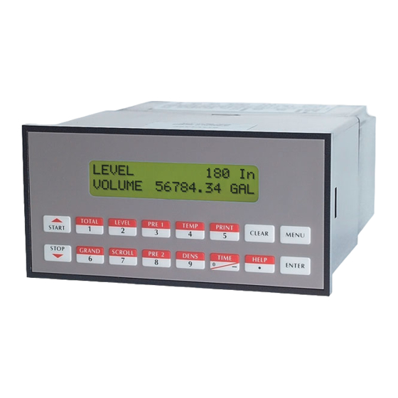
1. Description Unit Description 1.1 Unit Description: The LEVELtrol-II satisfies the requirements for a variety of level instrument needs. Multiple equations and instrument functions for a variety of tank shapes are available in a single unit with many advanced features. -
Page 6: Specifications
LEVELtrol-II Installation & Operating Instructions 1.3 Specifications: Specifications: Compensation Input Environmental The compensation input is menu selectable for Indoor Use temperature, density or not used. Altitude up to 2000m Operating Temperature: 0°C to +50°C Operation: Ratiometric (-20°C to 55°C optional) Accuracy: 0.01% FS... - Page 7 LEVELtrol-II Installation & Operating Instructions Analog Output Operating Mode The analog output is menu assignable to The LEVELtrol-II can be thought of as making a correspond to the Uncompensated Volume Level, series of measurements of level, temperature/ Corrected Volume Level, Mass, Temperature, density sensors and then performing calculations Density.
- Page 8 Setup Mode Maintenance Mode: The setup mode is password protected by means The Maintenance Mode of the LEVELtrol-II is the of a numeric lock out code established by the user. Test and Calibration Mode for the device. This In addition, a secret, manufacturers numeric unlock mode provides a number of specialized utilities entry sequence is available.
- Page 9 Operation of Serial Port with Modems (optional) starting point for your application. This permits the user to have an excellent starting point and helps The LEVELtrol-II RS-232 channel may be used with speed the user through the instrument setup. a modem in remote metering applications.
-
Page 10: Installation
2.1 General Mounting Hints: Hints The LEVELtrol-II Flow Computer should be located in an area with a clean, dry atmosphere which is relatively free of shock and vibration. The unit is installed in a 5.43" (138mm) wide by 2.68" (68mm) high panel cutout. (see Mounting... -
Page 11: Applications
• Relay Outputs Level or Tank Volume Alarms Applications: The LEVELtrol-II can monitor actual liquid level and tank volume of a liquid. Alarms are provided via relays and datalogging is available via analog (4- 20mA) and serial outputs. Tank Level/ Volume... -
Page 12: Corrected Tank Volume
• Corrected Tank Volume is calculated using the level and temperature inputs as well as the liquid's thermal expansion coefficient stored in the LEVELtrol-II. Use the "SET FLUID PROPERTIES" submenu to define reference temperature and density values for standard conditions. -
Page 13: Total Mass In Tank
LEVELtrol-II Installation & Operating Instructions Total Mass in Tank 3.3 Total Mass in Tank Measurements: Actual level is measured by the level sensor (ultrasonic, hydrostatic or differential pressure transmitter). Temperature is measured by the temperature transmitter. A density transmitter can alternately be used for direct density measurements. -
Page 14: Batching Volume, Corrected Volume Or Mass From Tank Level
LEVELtrol-II Installation & Operating Instructions Batching Volume, 3.4 Batching Volume, Corrected Volume or Mass from Tank Level Corrected Volume or Mass from Tank Level Measurements: A Level transmitter measures the liquid level in a tank. A temperature sensor can also be installed to correct for liquid thermal expansion (see 3.2 Corrected Volume). -
Page 15: Wiring
LEVELtrol-II Installation & Operating Instructions 4 WIRING 4.1 Typical Batcher Wiring: Batcher Wiring (+) V DC OUTPUT LEVEL Signal Iin + Level Sensor COMMON --------- Vin + RTD EXCIT + COMP RTD SENS Iin + RTD SENS - Stop Start... -
Page 16: Wiring In Hazardous Areas
LEVELtrol-II Installation & Operating Instructions 4.3 Wiring In Hazardous Areas: Examples using MLT787S+ Barrier (MTL4755ac for RTD) Level Input Flow Input Hazardous Area Safe Area 4-20mA 4-20 24V Out Diode Transmitter Q/∆P – 4-20mA In Common Temperature or Temperature/Density Input (4-20mA Transmitter) -
Page 17: Unit Operation
LEVELtrol-II Installation & Operating Instructions 5. UNIT OPERATION 5.1 Front Panel Operation Concept for Run Mode The LEVELtrol-II is fully programmable through the front panel. Please review the following usage summary before attempting to use the instrument. TOTAL LEVEL PRE 1... -
Page 18: General Operation
LEVELtrol-II Installation & Operating Instructions 5.2 General Operation General Operation The unit can display: Level, Available Total, Gross Total, Temperature, Density, Presets and Time of Day. The Temperature and/or Density can be displayed even if you are using the Volumetric Flow Equation (a Temperature or Density sensor must be installed). -
Page 19: Analog Output In Level/Total Mode
LEVELtrol-II Installation & Operating Instructions 5.3.4 Analog Output in Level/Total mode Analog Output (Level/Total mode) The analog output is menu assignable to correspond to the Level, Volume, Corrected Volume, Mass, Temperature, Density. The analog output is ideal for "trend" tracking using strip chart recorders or other devices. -
Page 20: Batcher Operation
LEVELtrol-II Installation & Operating Instructions 5.4 Batcher Operation Batcher Operation The Batcher mode is used primarily to dispense batches of fluid based on changes in tank volume as indicated by tank level. The main difference between the Batch mode and Level/Total mode is the relay operation. -
Page 21: Password Protection For Batcher Mode
LEVELtrol-II Installation & Operating Instructions 5.4.2 Password Protection for Batcher Mode Password Protection (Batch mode) After an Operator and/or Supervisor Password is defined in the setup mode (see section 6.3, SETUP PASSWORD submenu), the unit will be locked. The unit will prompt the user for the password when trying to enter the menu. -
Page 22: Analog Output In Batcher Mode
LEVELtrol-II Installation & Operating Instructions 5.4.5 Analog Output in Batcher mode Analog Output (Batch mode) The analog output is menu assignable to correspond to the Tank Level, Temperature, Density, Volume Total, Corrected Volume Total or Mass Total. The analog output is ideal for "trend" tracking using strip chart recorders or other devices. -
Page 23: Programming
LEVELtrol-II Installation & Operating Instructions 6. PROGRAMMING 6.1 Front Panel Operation Concept for Program Mode The LEVELtrol-II is fully programmable through the front panel. Please review the following usage summary before attempting to use the instru- ment. TOTAL LEVEL PRE 1... -
Page 24: Ez Setup
LEVELtrol-II Installation & Operating Instructions 6.2 EZ Setup The EZ Setup routine is a quick and easy way to configure the unit for the most commonly used instrument functions. This setup assumes that you are measuring level using a 4-20 mA transmitter. Entering the EZ Setup mode automatically sets many features. - Page 25 LEVELtrol-II Installation & Operating Instructions Menus Display Notes 6.2.2 (continued) If VERT or HORZ selected, Enter tank TANK LENGTH EZ Setup length. Submenu Groups Enter the distance between the base of tank SENSOR LOCATION and the level sensor location. (Enter a negative value if the sensor is located below the tank)
-
Page 26: Setup Menus
LEVELtrol-II Installation & Operating Instructions 6.3 Setup Menus Menus Display Notes 6.3.1 Select Setup to enter the instrument setup SELECT OPERATE STATE Top Level Setup routine. Setup Test Menu MENU 6.3.2 Refer to Page 20 for Details. DO EZ SETUP? -
Page 27: Setup Sub-Menus
LEVELtrol-II Installation & Operating Instructions 6.4 Setup Sub-Menus Sub-menus Display Notes 6.4.1 Refer to page 19 for EZ Setup routine. DO EZ SETUP? DO EZ SETUP? Advance To If NO selected, advance to Set Instrument Type for general menu access and setup. -
Page 28: Setup Indicators (Vol)
LEVELtrol-II Installation & Operating Instructions Sub-menus Notes Display 6.4.3 Press ENTER to begin setup of indicators. SETUP INDICATORS SETUP INDICATORS (Vol) Press ENTER when Vol. is flashing to SETUP INDICATORS configure the Totalizer Indicators Vol. Mass Level Temp Enter the desired Total Descriptor... -
Page 29: Setup Indicators (Level)
LEVELtrol-II Installation & Operating Instructions Sub-menus Display Notes Press ENTER when Level is flashing to 6.4.5 SETUP INDICATORS SETUP configure the Level Indicators Vol. Mass Level Temp INDICATORS (Level) Enter the desired Descriptor for the Level LEVEL DESCRIPTOR Indicator. Level Enter the desired Level Units Label. -
Page 30: Setup Tank Style (Strapping Table)
LEVELtrol-II Installation & Operating Instructions Sub-menus Display Notes Press ENTER to begin the tank style 6.4.7 SETUP TANK STYLE SETUP TANK STYLE configuration. (Strapping Table) Press ENTER when TBL. is flashing to TANK SHAPE configure the Strapping Table. TBL. VERT HORZ SPHR... -
Page 31: Setup Tank Style (Vertical Cylindrical Or Horizontal Cylindrical)
LEVELtrol-II Installation & Operating Instructions Sub-menus Display Notes 6.4.8 Press ENTER to begin the tank style SETUP TANK STYLE SETUP TANK STYLE configuration. (Vertical Cylindrical Horizontal Press ENTER when VERT or HORZ. to select Cylindrical) TANK SHAPE vertical or horizontal tank. -
Page 32: Setup Process Inputs (Level)
LEVELtrol-II Installation & Operating Instructions Sub-menus Display Notes Press ENTER to begin setup of Process 6.4.10 SETUP PROCESS INPUTS SETUP PROCESS Inputs. INPUTS (Level) Press ENTER when Level is flashing to SETUP PROCESS INPUTS configure the Level Input. Level Compen/Input... -
Page 33: Setup Process Inputs (Compensation Input)
LEVELtrol-II Installation & Operating Instructions Sub-menus Display Notes Press ENTER when Compen/Input is flashing 6.4.11 SETUP PROCESS INPUTS SETUP PROCESS to configure the Compensation Input. Compen/Input Level INPUTS (Compensation Input) Select Temperature to set the Compensation COMPENSATION INPUT Input for Temperature inputs. -
Page 34: Set Fluid Properties
LEVELtrol-II Installation & Operating Instructions Sub-menus Display Notes Press ENTER at this prompt to begin the 6.4.12 SET FLUID PROPERTIES SET FLUID Fluid Properties setup. (See Appendix A) PROPERTIES Enter the Reference Density. REF. DENSITY ###### lbs/g Enter the Reference Temperature. -
Page 35: Setup Outputs (Pulse Output)
LEVELtrol-II Installation & Operating Instructions Sub-menus Display Notes Press ENTER when Pulse is flashing to setup 6.4.14 SETUP OUTPUTS SETUP OUTPUTS the Pulse Output. Pulse Analog (Pulse Output) Select the desired Pulse Output Usage. PULSE OUTPUT USAGE FILL DRAIN BOTH... -
Page 36: Setup Relays (Relay 2)
LEVELtrol-II Installation & Operating Instructions Sub-menus Display Notes 6.4.15 (continued) Select the desired Relay for setup. (Relay 1) SETUP RELAYS SETUP RELAYS Rly1 Rly2 Rly3 Rly4 (Relay 1) BATCH MODE Relay 1 is reserved for Preset in Batch mode. RELAY 1... -
Page 37: Setup Relays (Relay 3 & 4)
LEVELtrol-II Installation & Operating Instructions Sub-menus Display Notes 6.4.16 (continued) Select the desired Relay for setup. (Relay 2) SETUP RELAYS SETUP RELAYS Rly1 Rly2 Rly3 Rly4 (Relay 2) BATCH MODE Select the desired Relay 2 usage. RELAY 2 USAGE PRWRN LEV OVRUN more... -
Page 38: Setup Control Inputs (Level/Total)
LEVELtrol-II Installation & Operating Instructions Sub-menus Display Notes Press ENTER to begin the Control Input 6.4.18 SETUP CONTROL INPUTS SETUP CONTROL setup. INPUTS (LEVEL/TOTAL) Select the desired Control Input for setup. SETUP CONTROL INPUTS Input1 Input2 Input3 Control Inputs 1, 2 & 3 can be set for Print,... -
Page 39: Setup Realtime Clock (Date)
LEVELtrol-II Installation & Operating Instructions Sub-menus Display Notes Select Date to enter the date. 6.4.21 SETUP REALTIME CLOCK SETUP REALTIME Date Time CLOCK (Date) Enter the date. (Month, Day, Last two Digits of DATE: MONTH,DAY,YEAR Year) ##/##/#### Advance To SERIAL USAGE 6.4.22... -
Page 40: Set Print Output (Configure)
LEVELtrol-II Installation & Operating Instructions Sub-menus Display Notes 6.4.23 Press ENTER to setup print output. SETUP PRINT OUTPUT SET PRINT OUTPUT (Configure) Select Config to setup Printer Output. SETUP PRINT OUTPUT Config Select_list Enter Print Time, printer will print at this time... -
Page 41: Setup Passwords (Operator)
LEVELtrol-II Installation & Operating Instructions Sub-menus Display Notes 6.4.25 Press ENTER to setup passwords. SETUP PASSWORDS SETUP PASSWORDS (Operator) Press enter when Operator is flashing to select SETUP PASSWORDS Operator Password. Operator Supervisor Enter a 4 digit number to define the Operator OPERATOR PASSWORD Password. -
Page 42: Principle Of Operation
The hydrostatic pressure measured at the base of a tank is a function of the liquid level and the density of the fluid. The LEVELtrol-II provides for the connection of a compensated input, a temperature or density transmitter, which will enable accurate determination of the liquid level in the tank. -
Page 43: Computation Of Corrected Volume In Tank And Mass In Tank
LEVELtrol-II Installation & Operating Instructions 7.5 Computation of Corrected Volume in Tank and Mass in Tank The mass in the tank can be computed if the volume in the tank and the density are known. This instrument has menu selections which permit the user to compute and view the quantity in the tank in mass units. - Page 44 LEVELtrol-II Installation & Operating Instructions Utility Functions- Volume Equations for Various Tank Geometries STRAPPING TABLE Case Volume = Linearize(level) /• call 32 point table to get volume •/ VERT Case Volume = level • PI • Tank_Diameter / (4 • Vol_Conv_Factor) HORZ case full_volume = PI •...
-
Page 45: Calculating The Expansion Factor For A Fluid
LEVELtrol-II Installation & Operating Instructions 7.6 Calculating the Expansion Factor For a Fluid Calculating The liquid density is a function of the flowing temperature for many fluids. This unit Expansion Factor solves an equation which represents this physical property of the fluid. -
Page 46: Test, Service And Maintenance
LEVELtrol-II Installation & Operating Instructions 8. Test, Service and Maintenance 8.1 Test Menus Menus Display Notes Select Test to enter the instrument 8.1.1 test & calibration routine. SELECT OPERATE STATE TOP LEVEL Test NOTE: Supervisor (Service) password Setup TEST MENUS required to gain access to this mode. -
Page 47: Test Sub-Menus
LEVELtrol-II Installation & Operating Instructions 8.2 Test Sub-Menus Sub-menus Display Notes 8.2.1 Press Enter to view the audit trail information. Audit Trail Audit Trail Submenu Group The audit trail is viewed in this format: nnnnn= number of critical menu changes,... -
Page 48: Keypad Test Submenu Group
LEVELtrol-II Installation & Operating Instructions Sub-menus Display Notes 8.2.4 Keypad test Keypad test Submenu Group Press the various keys and the display will show the key that was pressed. Press Menu to exit the test Keypad test Key pressed—> ENTER Press Menu to get back to Keypad test top- level menu. -
Page 49: 8.2.16 Calibration Submenu Group
LEVELtrol-II Installation & Operating Instructions ALL UNITS ARE CALIBRATED AT THE FACTORY PRIOR TO SHIPMENT CAUTION: This unit must be calibrated using precision and calibrated equipment. Equipment needed is as follows: Digital Multimeter, Precision Current/Voltage Source, Oscilloscope, Frequency Counter. Sub-menus... - Page 50 LEVELtrol-II Installation & Operating Instructions Sub-menus Display Notes TB1-8, (-) TB1-4. Input 0mA and press Enter. 8.2.8 Calibrate ch2 Calibrate CH2 0mA Iin=TB1-8 GND=TB1-4 Submenu Group This message is displayed during calibration. Calibrate ch2 0 CALIBRATING —— This message is displayed when the 0mA calibration is finished.
- Page 51 LEVELtrol-II Installation & Operating Instructions Sub-menus Display Notes To Calibrate: Connect Voltage Source (+) 8.2.10 Calibrate ch1 Calibrate CH1 0V TB1-2, (-) TB1-4. Input 0V and press Enter. Vin=TB1-2 GND=TB1-4 Submenu Group This message is displayed during calibration. Calibrate ch1 0 CALIBRATING ——...
- Page 52 LEVELtrol-II Installation & Operating Instructions Sub-menus Display Notes To Calibrate: Connect Voltage Source (+) 8.2.12 Calibrate ch2 Calibrate CH2 0V TB1-5, (-) TB1-4. Input 0V and press Enter. Vin=TB1-5 GND=TB1-4 Submenu Group This message is displayed during calibration. Calibrate ch2 0 CALIBRATING ——...
-
Page 53: Analog In Test Submenu Group
LEVELtrol-II Installation & Operating Instructions Sub-menus Display Notes Connect ammeter to (+) TB1-15, (-) TB1-16. 8.2.15 Calibrate 4mA out Calibrate 4mA Out Press enter. + TB1-15 - TB1-16 Submenu Group To trim 4mA output: Press CLEAR to enable Calibrate 4mA out editing and enter the current reading that is on Enter mA: 4.00000... -
Page 54: Analog Out Test Submenu Group
LEVELtrol-II Installation & Operating Instructions Sub-menus Display Notes Press Enter to test the analog output. 8.2.18 Analog out test Analog out test Submenu Group To simulate analog output: Connect an ammeter to (+) TB1-15, (-) TB1-16. Press the key under the desired setting to move the Analog out test asterisk (*). -
Page 55: Battery Voltage Test Submenu Group
LEVELtrol-II Installation & Operating Instructions Sub-menus Display Notes 8.2.22 Press Enter key to view the battery voltage. Battery Voltage Test Battery Voltage test Submenu Group The display will show the battery voltage. Battery Voltage Test Replace battery at 2.2 VDC or below. -
Page 56: Internal Fuse Replacement
LEVELtrol-II Installation & Operating Instructions 8.3 Internal Fuse Replacement Instructions: 1. Make sure you follow proper E.S.D. Precautions. All persons performing this replacement must follow proper grounding procedures. 2. Turn the power to the unit off. 3. Disconnect the two piece connector rear terminal block, leaving all connections in place. -
Page 57: Rs-232 Serial Port
LEVELtrol-II Installation & Operating Instructions 9. RS-232 Serial Port 9.1 RS-232 Port Description: The LEVELtrol-II has a general purpose RS-232 Port which may be used for any one of the following purposes: Transaction Printing Data Logging to Printer Remote Metering by Modem (optional) -
Page 58: Rs-485 Serial Port (Optional)
LEVELtrol-II Installation & Operating Instructions 10. RS-485 Serial Port (optional) 10.1 RS-485 Port Description: The LEVELtrol-II has a an optional general purpose RS-485 Port which may be used for any one of the following purposes: Accessing Process Parameters Level, Temperatures, Pressures, Density, Time & Date, Setpoints, etc. -
Page 59: Instrument Setup Software (Optional)
LEVELtrol-II Installation & Operating Instructions 11. Instrument Setup Software (optional) The LEVELtrol-II setup program provides for configuring, monitoring and controlling a LEVELtrol-II unit. Sample applications are stored in disk files. The setup program calls these Tem- plates. You can store the setup from the program’s memory to either the LEVELtrol- II (Downloading the file) or to a disk file (Saving the file) for later usage. -
Page 60: Using The Setup Software
3. Print the current setup information through the PC's printer using Print Setup option. 11.6 Setup Tab The Setup tab is where the majority of the LEVELtrol-II instrument setup modifications are done. The Setup tab is divided into five sections. System Section:... -
Page 61: View Tab
If communication errors occur while reading data from the LEVELtrol-II device, the word ‘Error’ will appear in place of the actual value. If the connection to the LEVELtrol-II is lost, the viewer will time out with a message saying the device is not responding. -
Page 62: Glossary Of Terms
A visual indication that the process is above or below the setpoint specified by the user. Analog Output The analog signal (4-20mA) that is generated by the LEVELtrol-II. It can correspond to the Level, Total, Temperature or Density. This output is used primarily for transmission of process information to remote systems. - Page 63 The capturing of information for later use and the mechanism for specifying the conditions where a capture should be made. DC Output / Excitation Voltage An on-board DC power supply used to power peripheral sensors. The LEVELtrol-II offers an excitation voltage of 24VDC when powered by AC voltage. Dec Places The number of digits to the right of the decimal point.
- Page 64 Preset A set point used to trigger the relay outputs of the LEVELtrol-II. Print Interval The print interval allows the LEVELtrol-II to transmit information to the serial port at selectable time intervals. Print Time The time of day at which the LEVELtrol II will transmit information to the serial port.
- Page 65 12. Glossary Of Terms (Continued) Pulse Output The pulse output of the LEVELtrol-II is available for remote accumulation of the delivery totals or batch totals into or out of the tank. The output can be scaled using the Pulse Output Scaling Constant.
-
Page 66: Diagnosis And Troubleshooting
LEVELtrol-II Installation & Operating Instructions 13. Diagnosis and Troubleshooting 13.1 Response of LEVELtrol-II on Error or Alarm: Error and warning indications which occur during operation are indicated in the RUN mode alternately with the measured values. The instrument has three types of error:... -
Page 67: Diagnosis Flow Chart And Troubleshooting
LEVELtrol-II Installation & Operating Instructions 13.2 Diagnosis Flow Chart and Troubleshooting All instruments undergo various stages of quality control during produc- tion. The last of these stages is a complete calibration carried out on state-of-the-art calibration rigs. A summary of possible causes is given below to help you identify faults. -
Page 68: Error & Warning Messages
LEVELtrol-II Installation & Operating Instructions 13.3 Error & Warning Messages: 13.3.1 Error/Warning Message Cause Remedy Sensor/Process Alarms COMP INPUT TOO LOW 4-20 mA Input current at • Check wiring comp input smaller than • Check function of 3.5 mA: sensor •... -
Page 69: Error & Warning Messages: (Continued)
LEVELtrol-II Installation & Operating Instructions 13.3 Error & Warning Messages: (Continued) 13.3.2 Error/Warning Message Cause Remedy Self Test Alarms BATTERY LOW WARNING Battery voltage too low • Replace Battery • Consult Factory for service information A to D NOT CONVERTING Fault in analog/digital •... -
Page 70: Common Fluid Properties Table
LEVELtrol-II Installation & Operating Instructions Appendix A Fluid Properties Table LIQUID FLUID REF. REF. COEFF. OF DENSITY TEMP. (ºF) EXPANSION (lb./gal) (e-6 format) 7.2947 -317.8 1626.2 0.172 AMMONIA 5.6996 -28.2 570.4 0.00157 2228.25 ARGON 11.6172 -302.6 1486.1 0.011291 511.34 8.735 -10.0... -
Page 71: Setup Menus
LEVELtrol-II Installation & Operating Instructions APPENDIX B... -
Page 72: Rs485 Modbus Rtu Protocol
If a reply is required, the LEVELtrol-II will construct the reply message and send it using Modbus RTU protocol. - Page 73 (RS-485 adaptor) and at the last device in the RS-485 chain and nowhere else. On the LEVELtrol-II this is accomplished by connecting a jumper from terminal 7 to terminal 4 or 8 at the RS-485 port when DB-9 connector is used. Place jumper between terminals 2 and 4 when the terminal block option is used.
- Page 74 LEVELtrol-II Installation & Operating Instructions Appendix C - RS485 Modbus RTU Protocol Register & Coil Usage Register Usage (each register is 2 bytes) LEVELtrol-II Data Register Data Type Access Level Reg 40001 & 40002 Float Read Unused Reg 40003 & 40004 –...
- Page 75 LEVELtrol-II Installation & Operating Instructions Appendix C - RS485 Modbus RTU Protocol Coil Usage (continued) LEVELtrol-II Data Coil Data Type Access Unused Coil 00014 – – Unused Coil 00015 – – Unused Coil 00016 – – Unused Coil 00017 –...
- Page 76 LEVELtrol-II Installation & Operating Instructions DECODING PART NUMBER Example Series: LT2 = LEVELtrol II WARRANTY Display Type: L= LCD O = OLED This product is warranted against V= VFD defects in materials and workman- Input Type: 1= 110 VAC ship for a period of two (2) years from...
Need help?
Do you have a question about the LEVELtrol-II and is the answer not in the manual?
Questions and answers