Table of Contents
Advertisement
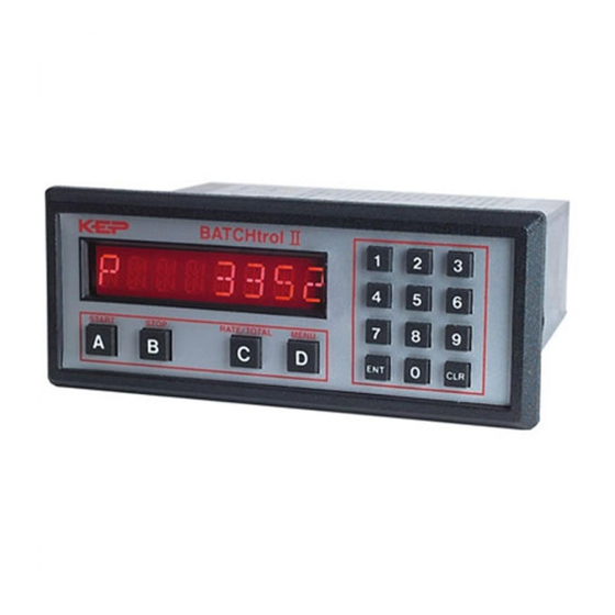
BATCHtrol II
Software Versions 8.x & 12.x
Installation and Operating Manual
Description
The Batcher is a programmable, microprocessor based unit which provides batch control, monitors flow
rate and controls the flow of processing liquids. Start/Stop controls can be used in conjunction with pre-
warn and final relays to provide valve actuation or pump control. An optional configuration offers stream-
lined preset adjustments, remote Start, Stop & Reset, and weighted averaging.
Features
❑ Pulse or Analog Input
Pulse or Analog Input
❑ Display Batch, Rate or Grand Total
Display Batch, Rate or Grand Total
Pulse Count Input up to 20 KHz
❑ Pulse Count Input up to 20 KHz
Pulse Count Input up to 20 KHz
16 Point Linearization
❑ 16 Point Linearization
16 Point Linearization
8 Digit K-Factors for Rate and Total
❑ 8 Digit K-Factors for Rate and Total
8 Digit K-Factors for Rate and Total
8 Digit K-Factors for Rate and Total
❑ Security Lockout
Security Lockout
❑ 2-Way RS232/422 Communications
2-Way RS232/422 Communications
NEMA 4X/IP65 Front Panel
❑ NEMA 4X/IP65 Front Panel
NEMA 4X/IP65 Front Panel
Scalable 4-20 mA Output
❑ Scalable 4-20 mA Output
Scalable 4-20 mA Output
Scaled Pulse Output
❑ Scaled Pulse Output
Scaled Pulse Output
❑ Optional Configuration Includes:
Optional Configuration Includes:
- Streamlined Preset Adjustment (Easy Preset)
- Streamlined Preset Adjustment (Easy Preset)
- Remote Start, Stop and Reset
- Remote Start, Stop and Reset
- Remote Start, Stop and Reset
- Weighted Averaging
- Weighted Averaging
Application
The unit is normally used for batch control or inventory tracking. The display may be toggled between
batch, rate, and grand total. A programmable K-factor makes keying-in engineering units easy. The unit
accepts pulse, contact closures or analog inputs and provides two separate preset controls.
Principle of Operation
The batcher receives an input from a pulse producing flowmeter through a sensor. The user programs
the batcher to condition the incoming pulses signal and compute the batch flow and flow rate. A wide
variety of different functions can then be performed based on the programmed configurations such as
start/stop functions, totalizing, and/or flow rate monitoring. Several other inputs, outputs and functions are
available.
99392 05/17/06
Visit us at www.TestEquipmentDepot.com
Kessler-Ellis Products Co.
BATCHtrol II
BATCHtrol II Series Technical Manual
99 Washington Street
Melrose, MA 02176
Phone 781-665-1400
Toll Free 1-800-517-8431
Advertisement
Table of Contents
Troubleshooting

Related Manuals for KEP BATCHtrol II


Summary of Contents for KEP BATCHtrol II
- Page 1 flow and flow rate. A wide variety of different functions can then be performed based on the programmed configurations such as start/stop functions, totalizing, and/or flow rate monitoring. Several other inputs, outputs and functions are available. 99392 05/17/06 BATCHtrol II Series Technical Manual...
- Page 2 SAFETY INSTRUCTIONS The following instructions must be observed. • This instrument was designed and is checked in accordance with regulations in force EN 60950 (“Safety of information technology equipment, including electrical business equipment”). A hazardous situation may occur if this instrument is not used for its intended purpose or is used incorrectly.
-
Page 3: Table Of Contents
CONTENTS 1. INTRODUCTION 1-1 General Description....................1 1-2 Typical Application....................1 1-3 Principles of Operation .....................1 1-4 STD PRE and EZ PRE Operation Modes ..............3 1-5 Specifications ......................4 1-6 Dimensions.......................5 2. INSTALLATION 2-1 Receipt of Equipment ....................6 2-2 Return Shipment.......................6 2-3 Panel Mounting......................6 2-4 Electrical Connections ....................6 2-5 Wiring Connections and Diagrams ................7 3. - Page 4 CONTENTS 6. TROUBLE SHOOTING AND MAINTENANCE GUIDE 6-1 Warning Messages....................34 6-2 Troubleshooting......................35 6-3 Removing The Case....................36 6-4 Maintenance ......................36 7. CALCULATING THE K FACTORS 7-1 General........................36 7-2 Calculating the K Factors ..................37 7-3 Calculating 16 Point K Factors ................39 8. SERIAL COMMUNICATIONS 8-1 Unit Code........................40 8-2 Baud Rate.......................40 8-3 Parity ........................40...
-
Page 5: Introduction
SECTION 1 INTRODUCTION 1-3 Principles of Operation 1-3 Principles of Operation Presets 1-1 General Description 1-1 General Description When the start button is pushed, two relays engage simultaneously to start flow. When Sections 1 through 8 of this manual describe the prewarn number is reached, one re- the wiring, programming and functionality of lay drops out. - Page 6 1-3 Principles of Operation 1-3 Principles of Operation (continued) Counter Frequency out The maximum count is 99999999. In the The Batcher generates a pulse out for each setup mode choose “RO” (Reset to Zero) for factored count. An NPN transistor output (Pin adding (count up) operation or “SP”...
-
Page 7: Std Pre And Ez Pre Operation Modes
1-4 STD PRE and EZ PRE Operation Modes 1-4 STD PRE and EZ PRE Operation Modes STD PRE and EZ PRE Operation Modes Version 8.7 of the batcher software allows the user to choose between STD PRE (Standard Preset) and EZ PRE (Easy Preset) operation modes. STD PRE operation is well suited for batch amounts that do not change, since the program mode must be entered to change the preset and the batch count must be cleared before starting a new batch. -
Page 8: Specifications
1-5 Specifications 1-5 Specifications Reset Housing: Front push button: “CLR” resets displayed High impact plastic case with NEMA 4X front number and control output. panel. Remote Input (Terminal 5): Open or 0 to 1 VDC (low), 3 to 30 VDC (high), 10K ohm input Dimensions: impedance to ground. -
Page 9: Dimensions
1-5 Specifications 1-5 Specifications (continued) 1-6 Dimensions Factored Output: One pulse per each factored count 3.31 Sinking (NPN Transistor) (84) Open Collector sinks 250 mA maximum to 1 volt maximum from 30 VDC maximum 8.17 Internal buffer: 9999 pulses (207.5) Output speed: user selectable (see table below) 7.375... -
Page 10: Installation
1-5 Dimensions (continued) SECTION 2 INSTALLATION 2-1 Receipt of Equipment 2-1 Receipt of Equipment When the equipment is received, the outside packing case should be checked for damage incurred during shipment. If the packing case is damaged, the local carrier should be notified at once regarding his liability. -
Page 11: Wiring Connections And Diagrams
2-4 Electrical Connections (continued) 2-5 Wiring Connections and Diagrams 2-5 Wiring Connections and Diagrams shielding is required for maximum noise im- munity. One end of the shielding should be ��������� connected to earth ground. Relays or induc- � � ����� � ������... -
Page 12: Front Panel Operation
Weighted Averaging 3-1 Front Panel Operation Version 8.7 of the batcher software includes weighted averaging of the rate display. Weighted averaging is not available on units with 16 Point Linearization. Weighted averaging can be used to create a more stable display when the rate input is fluctuating. START STOP RATE/TOTAL... -
Page 13: Ver 8.7 Programming
3-2 VER 8.8 Programming 3-3 VER 8.8 K-Factor Programming (See Programming Flow Chart, Page 10) Overview: The average sensor K-Factor is usually provided in This Section of the manual provides an outline of pulses per unit volume, and will have to be modified programming procedures for the batcher software before entering it into the instrument. -
Page 14: Software Version 8.7 Programming Flow Chart
Test Equipment Depot - 800.517.8431 - 99 Washington Street Melrose, MA 02176 FAX 781.665.0780 - TestEquipmentDepot.com... -
Page 15: Ver 12.0 Programming
3-5 VER 12.0 Programming 3-6 VER 12.0 16 Point Linearization Notes (See Programming Flow Chart, Page 12) (Unit with 16 Point Linearization) Overview: A K-Factor and a Frequency must be entered for at This Section of the manual provides an outline least three points on a unit with Linearization. -
Page 17: How To Program
3-8 How to Program 3-8 How to Program 3-9 Frequently Asked Questions About 3-9 Frequently Asked Questions About Setting Up The Batcher Setting Up The Batcher The initial programming of the unit is accom- Q. Is there any way to backspace if the wrong plished by first depressing the MENU button. -
Page 18: Setup Procedure For The Batcher
3-10 Setup Procedure For The Batcher 3-10 Setup Procedure For The Batcher MENU ITEM 1 PRESET PRESS DISPLAY PRESET ↓ ↓ Menu Button. Flashing PRESET number. Enters Preset Routine. 0 Flashes. Clears out existing PRESET. 1 2 3 4 1234 PRESET Flashes. Sample Preset. - Page 19 3-10 Setup Procedure For The Batcher 3-10 Setup Procedure For The Batcher (continued) MENU ITEM 3 PRE TYP This menu item is used to set up the Preset Type. PRESS DISPLAY PRESET ↓ ↓ PREWARN ↓ ↓ PRE TYP ↓ ↓ STD PRE ↓...
- Page 20 3-10 Setup Procedure For The Batcher 3-10 Setup Procedure For The Batcher (continued) MENU ITEM 4 COUNT (continued) PRESS DISPLAY R0 ↓ ↓ SP ↓ ↓ Store new K Factor. RO is Reset to zero. SP is Reset to Preset. This selection determines whether the unit counts up or counts down.
- Page 21 3-10 Setup Procedure For The Batcher 3-10 Setup Procedure For The Batcher (continued) MENU ITEM 5 RATE Setting the Ratemeter PRESS DISPLAY PRESET ↓ ↓ PREWARN ↓ ↓ PRE TYP ↓ ↓ COUNT↓ ↓ RATE↓ ↓ K FACTOR This selects the Ratemeter portion of the menu. K FACTOR flashes then shows the current Ratemeter K Factor.
- Page 22 3-10 Setup Procedure For The Batcher 3-10 Setup Procedure For The Batcher (continued) MENU ITEM 6 RATE (continued from previous page) From the previous page, we are in the SIG FIG setting portion of the Ratemeter setup Menu. PRESS DISPLAY SIG FIG ## Store new WINDOW.
- Page 23 3-10 Setup Procedure For The Batcher 3-10 Setup Procedure For The Batcher (continued) MENU ITEM 6 LOCKOUT This menu item uses a 4 digit security code to prevent unwanted changes in the programming or improper use of the Batcher. The unit is shipped from the factory with a security setting of 00 and a lockout code of 1000.
- Page 24 3-10 Setup Procedure For The Batcher 3-10 Setup Procedure For The Batcher (continued) From the previous page, we are in the CODE setting portion of the Lockout setup Menu. PRESS DISPLAY CODE Store new security time. Enters device routine to program in a 4 digit Lockout Code. The word CODE appears briefly then the current Lockout Code number is displayed.
- Page 25 3-10 Setup Procedure For The Batcher 3-10 Setup Procedure For The Batcher (continued) MENU ITEM 7 OUTCARD If the unit is equipped with a serial communications card, the setup parameters in the following menu will make the Batcher compatible with the master terminal. The Unit Identification Num- ber (if multiple units are used), Baud Rate (speed at which the signal is transmitted) and Parity are selectable.
- Page 26 3-10 Setup Procedure For The Batcher 3-10 Setup Procedure For The Batcher (continued) From the previous page, we are in the BAUDRATE setting portion of the Outcard setup Menu. PRESS DISPLAY By pressing the D button repeatedly, the available Baud rates will be displayed. The menu will cycle through the rates again whenever the bottom of the list is reached.
- Page 27 3-10 Setup Procedure For The Batcher 3-10 Setup Procedure For The Batcher (continued) MENU ITEM 8 ALG OUT This section is for models of the batcher with the analog output feature. The Analog Output card is a (0 - 20) or (4 - 20) mA current sink. The low (0mA) or (4 mA) and high (20mA) set- tings may be set at any range.
- Page 28 3-10 Setup Procedure For The Batcher 3-10 Setup Procedure For The Batcher (continued) From the previous page, we are in the SET HIGH setting portion of the ALG OUT setup Menu. PRESS DISPLAY 0 Flashes. Clears out existing High Setpoint value. 6 7 5 9 D 5 6759.5 Flashes.
- Page 29 3-10 Setup Procedure For The Batcher 3-10 Setup Procedure For The Batcher (continued) MENU ITEM 10 16 POINT This section is for models of the Batcher which have 16 Point Linearization. This option al- lows the user to key in from 3 to 16 different frequency points (inputs per second) and assign different K Factors dividers from 0.00011 to 999999 for each of these frequen- cies.
- Page 30 3-10 Setup Procedure For The Batcher 3-10 Setup Procedure For The Batcher (continued) From the previous page, we are in the POINT setting portion of the 16 Point setup Menu. PRESS DISPLAY 1 2 3 4 then POINT 01 The unit displays the last frequency entered for Point 01. Clears out existing frequency for Point 01.
-
Page 31: Run Mode
3-11 Run Mode 3-11.3 Locking the Unit The unit is shipped from the factory unlocked. 3-11.1 The Display To lock the unit, it must be in the Run Mode. The In the Run Mode the display will initially dis- unit is shipped from the factory with a Lockout play: Code of 1000. - Page 32 3-11 Run Mode (continued) 3-11.4 Start and Stop Operation (continued). 3-11.4 Start and Stop Operation. The START button initiates the batch se- The Batcher is designed for batching opera- quence. Once the unit is started: a) The display will prompt the operator tions.
-
Page 33: Internal Operation
3-12 Internal Operation 3-12 Internal Operation 3-12.2 Analog Inputs and Computations 3-11.1 Digital Inputs and Computations The Analog input signal is filtered electronically and converted to a 0 - 10000 Hz input frequency. The 3-30 Volt input signal is filtered electroni- (See Section 7, K Factor Calculation and Sec- cally (See Section 4-1, Digital Pulse Inputs). -
Page 34: Inputs
SECTION 4 INPUTS 4-1 Digital Pulse Inputs 4-1 Digital Pulse Inputs (continued) 4-1 Digital Pulse Inputs 4-1 Digital Pulse Inputs (Terminal 4) 4-1.1 STANDARD: High Impedance (Terminal Digital Pulse Inputs: The input board is a Has a 10 K Ohm pull down resistor to ground separate board that is plugged into the mother (Terminal 12) and must be driven high. - Page 35 4-2 Analog Inputs 4-2 Analog Inputs (continued) 4-2.3 Analog Inputs Exchange 4-2.1 5A: 4-20 mA; 250 Ω input impedance. If an analog sensor cannot be obtained that 5B: 0-20 mA; 250 Ω input impedance. matches the Batcher input, it is recommended 5C: 1-5 VDC;...
-
Page 36: Dc Power Inputs
4-3 DC Power Inputs 4-3 DC Power Inputs (Terminals 12, 14) SECTION 5 OUTPUTS The Batcher may be powered by an external The Batcher has five different possible types DC power supply. The supply must provide 12 of outputs for controlling external devices or - 27 Volts DC and at least 280 mA of current. -
Page 37: Control Outputs
5-1.2 Internal Buffer for Frequency Output 5-1.2 Internal Buffer for Frequency Output 5-2.2 Open Collector Version 5-2.2 Open Collector Version (Terminal 19, 20). An internal buffer will store up to 9,999 counts The NPN, Open Collector Transistors, sink a if the scaled input generates pulses faster than maximum of 250 mA at 30 VDC when active. -
Page 38: Optional Rs232 / Rs422 Serial Communications
5-3 Optional Analog Output 5-3 Optional Analog Output (continued) SECTION 6 TROUBLE SHOOTING AND MAINTENANCE GUIDE 4-20 mA Out Wiring 4-20 mA Out Wiring 6-1 Warning Messages 6-1 Warning Messages 6-1.1 PREWRONG Indicates that the values in Preset and Prewarn are not acceptable. -
Page 39: Troubleshooting
6-1 Warning Messages 6-1 Warning Messages (continued) 6-2.2 Problems Symptom: Unable to start batch. 6-1.5 BAD FREQ Possible Cause #1: Displayed Batch count al- Indicates that the values in the 16 Point setup ready exceeds the Preset value. are not acceptable. This condition will occur Test Procedure: Check Preset value against when the frequency values are not in ascending the displayed value. -
Page 40: Removing The Case
6-3 Removing the Case 6-3 Removing the Case SECTION 7 CALCULATING THE K FACTORS To install or change the input or data interface Remove cards, the case must be removed. 7-1 General all power before opening the case. all power before opening the case. CMOS The key to accurate flow measurement with logic is used so observe standard precautions the Batcher is correct scaling. -
Page 41: Calculating The K Factors
Step 4. 7-2 Calculating the K Factors. 7-2 Calculating the K Factors. Enter the Count K-Factor as de- The following steps are the recommended scribed in Section 3-3 referencing procedure forcalculating the K Factors. Take the Programming Flowchart (3-4) your time and go through the procedure slow- as needed. - Page 42 Step 3. The Count K Factor may be computed 7-2.2 Calculating the K Factor for Analog 7-2.2 Calculating the K Factor for Analog Inputs. Inputs. as follows: Obtain the Flow Rate value that corresponds Count K-Factor = Sensor K-Factor to the meters full scale signal. This should be specified on your device or with its paper Example: Count K-Factor of 3000 /10 = work.
-
Page 43: Calculating 16 Point K Factors
7-3 Calculating 16 Point K Factors 7-3 Calculating 16 Point K Factors the auto-ranging decimal point in the rate display will be shifted to the left as the dummy decimal is shifted to the left. This is so that the rate dis- Units equipped with the 16 Point option allow the play will be as same as the count. -
Page 44: Serial Communications
SECTION 8 SERIAL COMMUNICATIONS 8-3 Parity 8-3 Parity Parity is a bit of information that is insert- This section applies to units which have the ed before the stop bit and is used to help Serial Communications interface option. Up check if the transmission is correct. -
Page 45: Rs232 Card Wiring
8-5 RS232 Card Wiring 8-5 RS232 Card Wiring 8-6 RS422 Electrical Requirements 8-6 RS422 Electrical Requirements This option has a subminiature D, 25 pin, fe- The input of the Batcher follows the standard male connector and is wired as a DCE (Data EIA high impedance minimum of 12 K Ohms. -
Page 46: Rs422 Card Wiring
8-7 RS422 Card Wiring 8-7 RS422 Card Wiring 8-7.2 RS422 Wiring Notes 8-7.2 RS422 Wiring Notes This option has a subminiature D, 37 pin, fe- The Batcher requires only four wires for male connector and is wired as a DCE (Data RS422 communication: Communications Equipment) device. -
Page 47: Strobe Wiring
8-9 Strobe Wiring 8-9 Strobe Wiring proper serial transmit codes to request data or set a new value. (See Section 8-10.2 8-9.1 RS232 Strobe Wiring 8-9.1 RS232 Strobe Wiring (RS232, 25 Pin RS232/RS422 Serial Input Codes). Up to 80 Connector) characters of data may be linked together and The 3 data lines are hooked up to Pins 9, 10, transmitted to the Batcher (as long as there... - Page 48 8-10.2 RS232/RS422 Serial Input Codes 8-10.2 RS232/RS422 Serial Input Codes 8-10.3 RS232/RS422 Serial Input Examples 8-10.3 RS232/RS422 Serial Input Examples Example A: (S) = Space Transmit from terminal Receive from Batcher DXX(S) (Device and address number followed D13(S) [Unit 13 activated] Device #13 by space) activates the Batcher that had...
-
Page 49: Strobe Address Operation
8-10.5 RS232/RS422 16 Point Serial Input 8-10.5 RS232/RS422 16 Point Serial Input in at the positive edge of a 3 to 30 VDC strobe Example Example input that remained high a minimum of 25 mil- liseconds. Requests are processed on a non- Example : (S) = Space priority basis. -
Page 50: Programming Worksheet
9 Programming Worksheet Model # _____________________________ Serial # _____________________________ Unit # ______________________________ PRESET _ _ _ _ _ _ _ _ OUTput FREQuency 20000 ■ PREWARN _ _ _ _ _ _ _ _ 2000 ■ PREset TYPe EZ PRE STD PRE ■... - Page 51 NEMATROL 4X2 - NEMA 4X/IP 65 Enclosure for NOT LIMITED TO THE IMPLIED WARRANTIES wall mounting accommodating 2 ‘TROL Series unit. OF MERCHANTABILITY AND FITNESS FOR A FLEXCOVER #36120 PARTICULAR PURPOSE. XTROL7/4- Explosion proof housing Visit us at www.TestEquipmentDepot.com Back to the KEP BATCHtrol II Page...
Need help?
Do you have a question about the BATCHtrol II and is the answer not in the manual?
Questions and answers