
Related Manuals for Icom IC-F43DT


Summary of Contents for Icom IC-F43DT
- Page 1 INSTRUCTION MANUAL UHF TRANSCEIVER IC-F43DT/DS This device complies with Part 15 of the FCC Rules. Operation is subject to the condition that this device does not cause harmful interference.
-
Page 2: Explicit Definitions
This transceiver will perform best if the microphone is 2 to 4 in. (5 instruction manual contains important operating instructions for the IC-F43DT/DS UHF TRANSCEIVER. to 10 cm) away from the lips and the transceiver is vertical. R CAUTION! NEVER operate the transceiver with a headset or other audio accessories at high volume levels. - Page 3 The use of non-Icom battery packs/chargers may impair transceiver performance and invalidate the warranty. For U.S.A. only CAUTION: Changes or modifications to this transceiver, not expressly approved by Icom Inc., could void your authority to operate this transceiver under FCC regulations.
-
Page 4: Table Of Contents
TABLE OF CONTENTS TABLE OF CONTENTS TABLE OF CONTENTS TABLE OF CONTENTS IMPORTANT ................ i IMPORTANT ................ i IMPORTANT ................ i IMPORTANT ................ i Printer connection ............ 25 Printer connection ............ 25 Printer connection ............ 25 Printer connection ............ 25 EXPLICIT DEFINITIONS ............. -
Page 5: Accessories
ACCESSORIES Supplied accessories Accessory attachments D Flexible antenna The following accessories are supplied: Qty. q Flexible antenna ……………………………………………1 Connect the supplied flexible anten- w Battery pack …………………………………………………1 na to the antenna connector. e Belt clip ………………………………………………………1 r Jack cover (with screws) ………………………………1 set CAUTION! •... - Page 6 ACCESSORIES ï Battery pack D Belt clip To attach the battery pack: To attach the belt clip: q Release the battery pack if it is attached. Slide the battery pack in the direction of the arrow (q), then w Slide the belt clip in the direction of the arrow until the belt lock it with the battery release button.
- Page 7 ACCESSORIES ï Jack cover Attach the jack cover when the optional speaker-microphone is not used. To attach the jack cover: To detach the jack cover: q Attach the jack cover on q Unscrew the screws with the [SP]/[MIC] jack. a Phillips screwdriver. w Tighten the screws.
-
Page 8: Panel Description
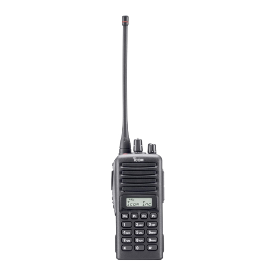
PANEL DESCRIPTION Front panel e DEALER-PROGRAMMABLE KEY [RED] Desired function can be programmed independently by your dealer. (p. 7) r [SP]/[MIC] JACK Connect the optional speaker-microphone. [SP]/[MIC] jack cover NOTE: Attach the [SP]/[MIC] jack cover when the optional speaker- microphone is not used. (See p. - Page 9 PANEL DESCRIPTION u 10-KEYPAD (Depending on version) !0 MONITOR KEY The keypad allows you to enter digits to: Mute and release the CTCSS (DTCS) or 2-tone squelch • Select memory channels mute. Open any squelch/deactivate any mute while • Select tone channels pushing this key.
-
Page 10: Function Display
PANEL DESCRIPTION Function display y AUDIBLE INDICATOR Appears when the channel is in the ‘audible’ (unmute) condition. Appears when the specified 2/5-tone/BIIS code is received. u COMPANDER INDICATOR Appears when the compander function is activated. i SCRAMBLER INDICATOR q TRANSMIT INDICATOR Appears when the voice scrambler function is activated. -
Page 11: Programmable Function Keys
This key’s operation depends on the Power ON Scan set- function keys. ting. Consult your Icom dealer or system operator for details con- cerning your transceivers programming. When the power ON scan function is turned OFF; If the programmable function names are bracketed in the fol- Push to start and cancel scanning operation. - Page 12 PANEL DESCRIPTION SCAN TAG KEY LOCK KEY Push to add or delete the selected channel to the scan group. Push and hold to electronically lock all programmable keys except the following: PRIORITY CHANNEL KEYS [Call] (incl. Call A and Call B), [Moni(Audi)] and [Emergency]. Push to select Priority A or Priority B channel.
- Page 13 PANEL DESCRIPTION DTMF AUTODIAL KEY TX CODE ENTER KEY (PMR or BIIS PMR operation only) Push to enter the DTMF channel selection mode. Then Push to enter the direct ID code edit mode, for both 5-tone select the desired DTMF channel using [CH Up]/[CH Down] and MSK.
- Page 14 PANEL DESCRIPTION COMPANDER KEY D For SmarTrunk operation only Push to toggle the compander function ON and OFF. TRUNKING GROUP KEY The compander function reduces noise components from the Push to select the Trunking group. transmitting audio to provide clear communication. TURBO SPEEDIAL A/B/C/D KEYS USER SET MODE KEY Push to automatically dial a commonly used number with one...
-
Page 15: Basic Operation
BASIC OPERATION Turning power ON Channel selection q Rotate [VOL] to turn the power ON. Several types of channel selections are available. Methods w If the transceiver is programmed for a start up passcode, may differ according to your system set up. input the digit codes as directed by your dealer. -
Page 16: Call Procedure
BASIC OPERATION Call procedure Receiving and transmitting When your system employs tone signaling (excluding CTCSS NOTE: Transmitting without an antenna may damage the and DTCS), the call procedure may be necessary prior to voice transceiver. See p. 1 for antenna attachment. transmission. - Page 17 BASIC OPERATION D Transmitting notes D TX code channel selection • Transmit inhibit function If the transceiver has [TX Code CH Select] assigned to it, The transceiver has several inhibit functions which restrict indication can be toggled between the operating channel transmission under the following conditions: number (or name) and TX code channel number (or name).
- Page 18 BASIC OPERATION D TX code number edit (PMR or BIIS PMR operation only) TO EDIT A TX CODE VIA [TX CODE ENTER] KEY: If the transceiver has [TX Code CH Select] or [TX Code q Select the desired TX code channel via [TX Code CH Up] Enter] assigned to it, TX code contents can be edited within or [TX Code CH Down].
-
Page 19: User Set Mode
BASIC OPERATION D DTMF transmission User set mode If the transceiver has [DTMF Autodial] assigned to it, the auto- matic DTMF transmission function is available. Up to 8 DTMF User set mode is accessed with [User Set Mode] and allows channels are available. -
Page 20: Biis Operation
BIIS OPERATION Default setting Receiving a call D D Individual call The following functions are assigned to each programmable q When an individual call is received; key as the default. However, the assigned function can be changed by your dealer. Ask your dealer for details. •... - Page 21 BIIS OPERATION D D Group call D D Displaying the received call record q When a group call is received; — Queue indication • Beeps sound. The transceiver memorizes the calling station IDs for record. • “ ” appears and the mute is released. Up to 3 calls can be memorized, and the oldest call record is •...
-
Page 22: Transmitting A Call
BIIS OPERATION Transmitting a call D D Calling back from the queue channel Total of a 3 ways for code selection are available—selecting q While in the standby condition, push [P1] (Digital) for the call code from memory, entering the call code from the 1 sec. - Page 23 BIIS OPERATION D D Direct code entry q While in the standby condition, push [P3] (TX Code Enter) u Push [PTT] to transmit; release to receive. i Push [MONITOR] (Moni(Audi)) to send the ‘Clear down’ to enter the TX code edit mode. •...
-
Page 24: Receiving A Message
BIIS OPERATION Receiving a message D D Receiving a status message D D Receiving an SDM q When a status message is received; q When an SDM is received; • Beeps sound. • Beeps sound. • The calling station ID (or text) and the status message is dis- •... - Page 25 BIIS OPERATION D D Received message selection e Push [UP] or [DOWN] to select the desired message. The transceiver memorizes the received messages for • When selecting the SDM that includes more than 8 characters, record. Up to 6 messages for status and SDM, or 95 charac- “...
-
Page 26: Transmitting A Status
BIIS OPERATION Transmitting a status D D General D D Transmitting a status q While in the standby condition, push [P1] (Digital), then The status message can be selected with the programmed text, and the message text is also displayed on the function push [UP] or [DOWN] to select the desired station/group display of the called station. -
Page 27: Transmitting An Sdm
BIIS OPERATION Transmitting an SDM D D General D D Transmitting an SDM q While in the standby condition, push [P1] (Digital), then The short data message, SDM, can be sent to an individual station or group stations. Also, 8 SDM memory channels are push [UP] or [DOWN] to select the desired station/group available and the messages can be edited via PC program- code. - Page 28 BIIS OPERATION D D Programming an SDM memory (10-keypad version is required) q During standby condition, push [P1] (Digital) twice, then • Available characters push [UP] or [DOWN] to select the desired SDM to be edit- Characters (’) (") w Push [M] or [#] to enter the message editing condition. (<) (>) •...
-
Page 29: Position Data Transmission
BIIS OPERATION Position data transmission Printer connection When the optional cable and a GPS receiver is connected to When the optional cable is connected to the transceiver, a the transceiver, the position (longitude and latitude) data can printer can be connected to print out the received SDM con- be transmitted automatically. -
Page 30: Auto Emergency Transmission
BIIS OPERATION Auto emergency transmission BIIS indication When [Emergency Single (Silent)] or [Emergency Repeat The following indications are available for the BIIS operation (Silent)] is pushed, an emergency signal is automatically on an MSK channel. transmitted for the specified time period. : Individual/group call is successful. -
Page 31: Battery Charging
BATTERY CHARGING BATTERY CHARGING BATTERY CHARGING BATTERY CHARGING Battery charging Battery charging Battery charging Battery charging Battery caution Battery caution Battery caution Battery caution CAUTION! NEVER CAUTION! NEVER CAUTION! NEVER CAUTION! NEVER Prior to using the transceiver for the first time, the battery Prior to using the transceiver for the first time, the battery Prior to using the transceiver for the first time, the battery Prior to using the transceiver for the first time, the battery... -
Page 32: Optional Battery Chargers
BATTERY CHARGING BATTERY CHARGING BATTERY CHARGING BATTERY CHARGING Optional battery chargers Optional battery chargers Optional battery chargers Optional battery chargers AD-106 installation AD-106 installation AD-106 installation AD-106 installation Install the AD-106 desktop charger adapter into the holder Install the AD-106 desktop charger adapter into the holder Install the AD-106 desktop charger adapter into the holder Install the AD-106 desktop charger adapter into the holder Connect the plugs of the BC-119N/BC-121N to the AD-106... - Page 33 • Six AD-106 charger adapters on version). on version). on version). on version). • An AC adapter (BC-124) • An AC adapter (BC-124) • An AC adapter (BC-124) • An AC adapter (BC-124) IC-F43DT/DS IC-F43DT/DS IC-F43DT/DS IC-F43DT/DS IC-F43DT/DS IC-F43DT/DS IC-F43DT/DS IC-F43DT/DS IC-F43DT/DS...
- Page 34 BATTERY CHARGING BATTERY CHARGING BATTERY CHARGING BATTERY CHARGING IMPORTANT: Ensure the sides of the battery pack are cor- IMPORTANT: Ensure the sides of the battery pack are cor- IMPORTANT: Ensure the sides of the battery pack are cor- IMPORTANT: Ensure the sides of the battery pack are cor- rectly aligned with the charger groves.
-
Page 35: Options
OPTIONS OPTIONS OPTIONS OPTIONS BATTERY PACK BATTERY PACK BATTERY PACK BATTERY PACK DC CABLES • CP-17L • CP-17L • CP-17L • CP-17L • BP-231 • BP-231 • BP-231 • BP-231 Li-Ion Li-Ion Li-Ion Li-Ion CIGARETTE LIGHTER CABLE CIGARETTE LIGHTER CABLE CIGARETTE LIGHTER CABLE CIGARETTE LIGHTER CABLE BATTERY PACK... -
Page 36: Safety Training Information
Radio Frequency Electromagnetic Fields, 3 kHz to 300 to Radio Frequency Electromagnetic Fields, 3 kHz to 300 from the body when transmitting and only use the Icom belt- from the body when transmitting and only use the Icom belt-... - Page 37 Electromagnetic Interference/Compatibility Electromagnetic Interference/Compatibility Electromagnetic Interference/Compatibility During transmissions, your Icom radio generates RF energy that During transmissions, your Icom radio generates RF energy that During transmissions, your Icom radio generates RF energy that During transmissions, your Icom radio generates RF energy that can possibly cause interference with other devices or systems.
- Page 38 MEMO...
- Page 39 MEMO...
- Page 40 A-6360H-1EX Printed in Japan 1-1-32 Kamiminami, Hirano-ku, Osaka 547-0003, Japan © 2004 Icom Inc.
Need help?
Do you have a question about the IC-F43DT and is the answer not in the manual?
Questions and answers