Table of Contents
Advertisement
Advertisement
Table of Contents

Subscribe to Our Youtube Channel
Related Manuals for Icom IC-F4011


Summary of Contents for Icom IC-F4011
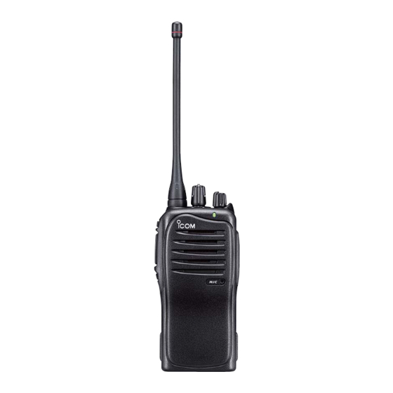
- Page 1 UHF TRANSCEIVERS S-14605XZ-C1 May. 2009...
- Page 2 8. READ the instructions of test equipment throughly before connecting a test equipment to the transceiver. Icom, Icom Inc. and ICOM logo are registered trademarks of Icom Incorporated (Japan) in the United States, the United Kingdom, Germany, France, Spain, Russia and/or other countries.
-
Page 3: Table Of Contents
TABLE OF CONTENTS SECTION SPECIFICATIONS SECTION INSIDE VIEWS SECTION DISASSEMBLY INSTRUCTION SECTION CIRCUIT DESCRIPITON RECEIVER CIRCUITS............4-1 TRANSMITTER CIRCUITS . -
Page 4: Specifications
• Antenna impedance • Operating temperature range : –30˚C to +60˚C (–22˚F to +140˚F) • Power supply requirement : Specified Icom's battery pack only (7.2 V DC nominal; negative ground) • Current drain (at 7.2 V DC ; approx.) RECEIVING TRANSMITTING Stand-by Max. - Page 5 SECTION 2. INSIDE VIEWS • MAIN UNIT TOP VIEW BOTTOM VIEW Pre-drive (Q5: 2SC3356) Power amplifier (Q7: RD07MVS2) Drive amplifier (Q8: RD01MUS2) AF amplifier (IC12: TA7368F) +5 Regulator (IC9: NJM2870F05) S5 Regulator Q23: 2SB1132 Q24: XP6501 Q25: UNR9113G0L T5 Regulator Crystal filter (Q21: 2SA1577) (FI1: FL-335)
- Page 6 SECTION 3. DISASSEMBLY INSTRUCTION 1. REMOVING THE CHASSIS UNIT 2. REMOVING THE MAIN UNIT q Unscrew 1 nut A, and remove 2 knobs B, C. q Unscrew 2 nuts F, and remove the top plate G. w Unscrew 2 screws D. w Unsolder 5 points H, and remove the shield cover.
-
Page 7: Circuit Descripiton
SECTION 4. CIRCUIT DESCRIPTION 4-1 RECEIVER CIRCUITS 4-1-1 ANTENNA SWITCHING CIRCUIT The antenna switching circuit functions as a low-pass filter The RF signals from the bandpass filter are mixed with the while receiving and a resonator circuit while transmitting. 1st LO signals, where come from the RX VCO circuit via the This circuit does not allow transmit signals to enter the BPF (L38, C49, C304, C305), at the 1st mixer circuit (Q3) receiver circuits. -
Page 8: Transmitter Circuits
4-1-5 AF AMPLIFIER CIRCUIT • CTCSS AND DTCS The tone squelch circuit detects tone signals and opens the The AF amplifier circuit amplifies the demodulated AF sig- squelch only when receiving a signal containing a matched nals to drive a speaker. subaudible tone (CTCSS or DTCS). - Page 9 4-2-2 MODULATION CIRCUIT The modulation circuit modulates the VCO oscillating signal 4-2-4 APC CIRCUITS (RF signal) using the audio signals from the microphone. The bias current of the drive (Q8) and power (Q7) amplifiers are controlled by the APC circuit. The AF signals from the D/A converter (IC8, pin 3) change the reactance of varactor diode (D18) to modulate the oscil- The APC circuit (IC2, D1, D30) protects drive and power...
-
Page 10: Pll Circuits
4-3-2 VCO CIRCUITS 4-3 PLL CIRCUITS The VCO circuit contains a separate RX VCO (Q14, D16, 4-3-1 PLL CIRCUIT D22) and TX VCO (Q13, D17, D18, D21). The oscillated A PLL circuit provides stable oscillation for the transmit fre- signal is amplified at the buffer amplifiers (Q10, Q12) and quency and the receive 1st LO frequency. -
Page 11: Other Circuits
4-6 PORT ALLOCATION 4-4 OTHER CIRCUITS LED CONTROL CIRCUITS 4-6-1 D/A CONVERTER IC (IC8) The LED control circuit is composed of the LED driver (Q32) Port and LED (DS1). Description number name Outputs the modulation balance level The CPU outputs “RLED” and “TLED” signals from the pins control signal. - Page 12 4-6-2 CPU (IC13) Port Port Description Description number name number name Input port for the transceiver’s RLED Outputs receiving LED control signal. TEMP internal temperature detecting Outputs transmitting LED control signal. TLED signal. Input port for the detect signal for BATV connecting battery pack’s voltage.
-
Page 13: Adjustment Procedures
SECTION 5. ADJUSTMENT PROCEDURE 5-1 PREPARATION ¤ REQUIRED EQUIPMENTS EQUIPMENT EQUIPMENT SPECIFICATION SPECIFICATION Adjustment JIG cable Modified OPC-478U/UC (USB type) or "CS-F3010 ADJ" (Revision 1.0 or later) software (see the page 5-3) OPC-478 (RS-232 type) Frequency range : 300–3000 Hz Power attenuation : 30 dB Audio generator Attenuator... - Page 14 • CONNECTION OPC-478 (RS-232C type) to RS-232C port Standard signal generator to the antenna connector 0.1 µV to 32 mV (–127 dBm to –17 dBm) to USB port OPC-478U DO NOT transmit while (USB type) an SSG is connected to to USB port the antenna connector.
- Page 15 (3) Boot up Windows, and click the program group 'CS-F3010 ADJ’ in the ‘Programs’ folder of the [Start] menu, then CS-F3010 ADJ’s window appears. (4) Click ‘Connect’ on the CS-F3010’s window, then IC-F4011/F4013’s up-to-date condition appears as below. (5) Set or modify adjustment value as specified in the following guidances.
-
Page 16: Frequency Adjustments
5-2 FREQUENCY ADJUSTMENT 1) Select an adjustment item using cursor or [↑] / [↓] of the PC’s keyboard. 2) Set or modify the adjustment value as specifi ed using [←] / [→] of the PC’s keyboard, then push [ENTER]. ADJUSTMENT ADJUSTMENT ADJUSTMENT CONDITION OPERATION... -
Page 17: Transmit Adjustments
5-3 TRANSMIT ADJUSTMENT 1) Select an adjustment item using cursor or [↑] / [↓] of the PC’s keyboard. 2) Set or modify the adjustment value as specifi ed using [←] / [→] of the PC’s keyboard, then push [ENTER]. ADJUSTMENT ADJUSTMENT ADJUSTMENT CONDITION OPERATION... -
Page 18: Receive Adjustment
5-4 RECEIVE ADJUSTMENT 1) Select an adjustment item using cursor or [↑] / [↓] of the PC’s keyboard. 2) Set or modify the adjustment value as specifi ed using [←] / [→] of the PC’s keyboard, then push [ENTER]. ADJUSTMENT ADJUSTMENT ADJUSTMENT CONDITION OPERATION... -
Page 19: Parts List
SECTION 6. PARTS LIST [ANT UNIT] [CONNECT UNIT] PARTS PARTS DESCRIPTION DESCRIPTION LOCATION LOCATION L601 6200013010 S.COI 0.30-0.9-5TL 10.3N <COMO> 7.2/12.5 C501 4030017460 S.CER ECJ0EB1E102K 8.3/5.3 C502 4030016930 S.CER ECJ0EB1A104K 9.3/5.3 C601 4030017600 S.CER ECJ0EC1H080C 5.8/15.3 J501 6910016390 CON IMSA-9230B-1-02Z145-PT1 M.=Mounted side (T: Mounted on the Top side, B: Mounted on the Bottom side) S.=Surface mount 6 - 1... -
Page 20: Main Unit
[MAIN UNIT] [MAIN UNIT] PARTS PARTS DESCRIPTION DESCRIPTION LOCATION LOCATION 1110003201 S.IC TA31136FNG(EL) 51.8/19 6200007700 S.COI LQW2BHN22NJ03L [USA-06] B 84.3/34.5 1130008561 S.IC TC75S51F(TE85L,F) 68.9/21 6200007690 S.COI LQW2BHN18NJ03L [USA-07] 1140005991 S.IC MB15A02PFV1-G-BND-ERE1 38.3/35.7 6200007700 S.COI LQW2BHN22NJ03L [CSA-01] 1110005340 S.IC NJM12902V-TE1-#ZZZB 28.6/7.1 6200007690 S.COI LQW2BHN18NJ03L [CSA-02]... - Page 21 [MAIN UNIT] [MAIN UNIT] PARTS PARTS DESCRIPTION DESCRIPTION LOCATION LOCATION 7030005120 S.RES ERJ2GEJ 102 X (1K) [USA-06] B 75.9/33.7 7030008410 S.RES ERJ2GEJ 392 X (3.9K) [USA-06] B 49.4/39.9 7030005240 S.RES ERJ2GEJ 473 X (47K) [USA-07] 7030009140 S.RES ERJ2GEJ 272 X (2.7K) [USA-07] 7030005120 S.RES ERJ2GEJ 102 X (1K) [CSA-01] 7030008410 S.RES ERJ2GEJ 392 X (3.9K) [CSA-01]...
- Page 22 [MAIN UNIT] [MAIN UNIT] PARTS PARTS DESCRIPTION DESCRIPTION LOCATION LOCATION R182 7030005090 S.RES ERJ2GEJ 104 X (100K) 24.7/39.1 R296 7030003490 S.RES ERJ3GEYJ 272 V (2.7K) 92.8/35.5 R183 7030006020 S.RES RR0510P-682-D (6.8K) 17.2/39.1 R297 7030005120 S.RES ERJ2GEJ 102 X (1K) 91.1/36.4 R184 7030008250 S.RES RR0510P-562-D (5.6K) 17.7/40.4...
- Page 23 [MAIN UNIT] [MAIN UNIT] PARTS PARTS DESCRIPTION DESCRIPTION LOCATION LOCATION 4030017340 S.CER ECJ0EC1H010B [USA-06] B 69/37.8 C110 4030017730 S.CER ECJ0EB1E471K 55.7/30.5 4030017550 S.CER ECJ0EC1H1R5B [USA-07] C111 4030017420 S.CER ECJ0EC1H470J 56.3/34.4 4030017340 S.CER ECJ0EC1H010B [CSA-01] C112 4030017460 S.CER ECJ0EB1E102K 60.2/38.6 4030017550 S.CER ECJ0EC1H1R5B [CSA-02] C113 4030017520 S.CER ECJ0EC1H0R3B...
- Page 24 [MAIN UNIT] [MAIN UNIT] PARTS PARTS DESCRIPTION DESCRIPTION LOCATION LOCATION C175 4030017360 S.CER ECJ0EC1H030B [USA-06] B 94.9/41.4 C291 4030016780 S.CER ECJ0EB1C153K 25.7/10.9 4030017560 S.CER ECJ0EC1H2R5B [USA-07] C292 4030016930 S.CER ECJ0EB1A104K 25.7/13.9 4030017360 S.CER ECJ0EC1H030B [CSA-01] C293 4030017740 S.CER ECJ0EB1E821K 25.7/11.9 4030017560 S.CER ECJ0EC1H2R5B [CSA-02] C295...
- Page 25 SECTION 7. MECHANICAL PARTS [CHASSIS PARTS] [ANT UNIT] ORDER ORDER DESCRIPTION QTY. DESCRIPTION QTY. MP601 8510016350 2721 ANT PLATE 6910015910 ANT CONNECTOR 104 6910015860 IMSA-6277S-O2A-G [CONNECT UNIT] 2510001530 PSC-3650P-0806A2 <PRI> ORDER 8900009640 OPC-963 DESCRIPTION QTY. 8010019696 2775 CHASSIS-6 J501 6910016390 IMSA-9230B-1-02Z145-PT1 8210024550 2775 A-FRONT PANEL (Inc.
- Page 26 MP13(C) J1(C) MP36(C) MP35(C) MP8(C) MP31(C) MP1(C) MP17(C) ANT Unit S1(C ) MP29( C ) W2 ( C ) CONNECT Unit MP30( C ) S4 ( M ) MP32(C) R226 ( M ) MAIN Unit MP14(C) MP28 ( C ) MP25 ( C ) MP11 ( C ) J2(C)
- Page 27 SECTION BOARD LAYOUTS • MAIN UNIT (TOP VIEW) C148 R169 R155 C259 C152 C153 C151 R124 C277 R168 C278 R181 C285 R180 R156 C261 R117 R118 R172 R237 C284 R182 C260 R157 C154 C149 C155 C116 C126 R123 C173 C117 C134 R297 C136...
- Page 28 • MAIN UNIT (BOTTOM VIEW) [DEALER-PROGRAMMABLE KEY] [PTT SWITCH ] [DEALER-PROGRAMMABLE KEY ] R107 C209 R101 C208 C143 C141 C109 C206 C305 C287 C304 C197 C130 R183 C196 R100 C186 C300 C288 C105 C103 C111 C177 C160 R113 C289 C203 C144 R114 C138...
- Page 29 SECTION 9. BLOCK DIAGRAM MAIN UNIT MAIN/MAIN-B UNIT 3SK324 9 - 1...
-
Page 30: Voltage Diagram
SECTION VOLTAGE DIAGRAM • MAIN UNIT VCO5 ACZ1005Y 2SC4116 RX VCO 6.8K ACZ1005Y 6.8K ANT UNIT 2SK880 *C127 *C126 C211 1.8U 4. 7 R103 C118 R104 2SC4226 1 VCON 330K 1.8U 0.5P C102 2.5P 2 GND R301 *R80 CR-783 120K 2.8N 2.8N 0.001... - Page 31 Highway 17 Delta, B.C., V4K 5B8, Canada : http://www.icomspain.com Phone : +1 (604) 952-4266 Fax : +1 (604) 952-0090 E-mail : icom@icomspain.com : http://www.icomcanada.com E-mail : info@icomcanada.com Blacksole House, The Boulevard, Altira Business Park, Herne Bay, CT6 6GZ, UK Phone : +44 (01227) 741741...
- Page 32 S-14605XZ-C1 1-1-32, Kamiminami, Hirano-ku, Osaka 547-0003, Japan © 2009 Icom Inc.
Need help?
Do you have a question about the IC-F4011 and is the answer not in the manual?
Questions and answers