Table of Contents
Advertisement
Quick Links
Advertisement
Table of Contents

Related Manuals for SAB SABIP1300


Summary of Contents for SAB SABIP1300
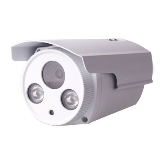
- Page 1 User Manual User Manual Outdoor HD IP Camera Model: SABIP1300 V1.0...
-
Page 2: Table Of Contents
User User Manual Manual Table of Contents Table of Contents.................................. 1 1 Overviews....................................2 1.1 Key Features................................3 1.2 Read Before Use..............................3 1.3 Packing Contents..............................4 1.4 Physical Description...............................4 1.4.1 Front Panel..............................4 1.4.2 Interface................................4 1.4.3 Bottom View..............................5 1.5 Wall installation............................... 5 2 Access the IP Camera..............................5 2.1 Hardware Connection &... -
Page 3: Overviews
User User Manual Manual 4.4.1 Video Settings............................41 4.4.2 On Screen Display............................42 4.4.3 Privacy Zone..............................43 4.4.4 Snapshot Settings.............................44 4.4.5 IR LED Schedule............................45 4.4.6 Lens Distortion Correction........................45 4.5 Alarm..................................46 Motion Detection..............................46 4.6 Record..................................49 4.6.1 Storage Location............................49 4.6.2 Local Alarm Location..........................49 4.7 Firewall................................... -
Page 4: Key Features
User User Manual Manual Outdoor HD IP Camera is an integrated IP Camera with a color CMOS sensor enabling viewing in High Definition resolution.It combines a high quality digital video camera, with a powerful web server, to bring clear video to your desktop from anywhere on your local network or over the Internet. The IP Camera supports the industry-standard H.264 compression technology, drastically reducing file sizes and conserving valuable network bandwidth. -
Page 5: Packing Contents
User User Manual Manual Installation Guide to avoid damage due to faulty assembly and installation. This also ensures the product is used properly as intended. 1.3 Packing Contents ● IPCAM×1 ● CD×1 ● DC Power Supply×1 ● Quick Installation Guide ×1 ●... -
Page 6: Bottom View
User User Manual Manual 10/100M adaptive Ethernet interface. Through this interface, IPCAM can be connected with various network devices, such as hub, router, etc. 2 Reset button Press and hold on the reset button for 5 seconds. Releasing the reset button, the password will back to the factory default administrator password. -
Page 7: Hardware Connection & Software Installation
User User Manual Manual 2.1 Hardware Connection & Software Installation 1. Connect the camera to the LAN network (Router or Switch) via network cable. 2. Connect the power adapter to the camera. 3. Insert the CD into the CD drive of your computer. 4. -
Page 8: Access The Camera In Wan
User User Manual Manual Go to Settings - Network - Port panel, you can see and change the HTTP and HTTPS port NO. Figure 2.3 NOTE: When logging in for the first time, you will need to download and install the add-on. Figure 2.4 2.3 Access the Camera in WAN 2.3.1 Static IP Addresses... -
Page 9: Remote Access
User User Manual Manual Figure 2.5 Access your IP Camera from the Internet You can access the IP Camera from the Internet (remote access). Enter the WAN IP address and port number in your standard browser. For example, you would enter http:// 183.37.28.254:88 2.3.2 Remote Access If you want to access your camera by web browser outside of your LAN, you need to configure following configurations. - Page 10 User User Manual Manual Select Yes and click Save. Figure 2.7 Click Enable DDNS and click Save. The content in the Manufacture’s DDNS column is the domain name of your camera. Figure 2.8 You can see the port of your camera here. If you want to set Remote Access for several cameras on the same network, you will need to change the HTTPS port for each camera.
- Page 11 User User Manual Manual Figure 2.10 If there is no UPnP function in your router: You need to manually add port(HTTPS port) forwarding, refer to the following steps. You need go to the “Forwarding > Virtual Servers” panel for setup. Click Add New.
-
Page 12: Using The Vlc Player
User User Manual Manual Here you have finished the Port Forwarding setup. Figure 2.13 5. Now you can access your IP camera by https://domain name: HTTPS port via the Internet. 2.4 Using the VLC player This camera supports RTSP streaming, here you can view the camera using VLC player. RTSP URL rtsp:// [user name][:password]@IP:port number/videosream The part in the square brackets may be omitted. - Page 13 User User Manual Manual Figure 2.14 Figure 2.15 Sometimes you may need to enter the user name and password again. Click OK and you can see the real-time preview.
-
Page 14: Ip Camera Connection To The Server
User User Manual Manual Figure 2.16 Figure 2.17 If you cannot play the video in the VLC player, please check the port mapping. You can read Quick Installation Guide about How to configure port forwarding. NOTE If you modify the camera’s username or password, you had better reboot the camera, or else the new username and password cannot take effect when you enter the authentication in the VLC. -
Page 15: Surveillance Software Gui
User User Manual Manual 3 Surveillance Software GUI Please refer to the section 2.1 if you install the camera for the first time. You can start to learn about software operation after finish quick installation. 3.1 Login Window Figure 3.1 Section1 Enter the Username and password The default administrator username is admin with no password, please change the password at first using and... -
Page 16: Surveillance Window
User User Manual Manual modification. You will now use the new username and password to login the camera in the future. Figure 3.2 3.2 Surveillance Window Figure 3.8... - Page 17 User User Manual Manual Section1 LiveVideo / Settings buttons : Path to surveillance window. Click this button and back to the surveillance window : Path to Administrator Control Panel, Click it, and it will lead to Administrator Control Panel and do advanced settings.
- Page 18 User User Manual Manual Select one of these Secondly: Click Start cruise button, the camera will cruise following the predefined path. Thirdly: Click stop button and finish cruising. Section4 IR LED Lights Click Infra led and there are three modes to adjust the infrared led: Auto, Manual and Schedule. Auto: Select it and the camera will adjust the infra led (on or off) automatically.
- Page 19 User User Manual Manual 1------Play Click it to play the video of the camera 2------Stop Click it to stop the video of the camera 3------ Talk: Click the button and the icon will become to , then talk to the microphone that connected with PC, people around the camera can hear your voice if the camera has connected with audio output device.
- Page 20 User User Manual Manual automatically. Sometimes there is a black border around the video, please select Keep ration to get a better visual quality. Figure 3.10 Full Screen: Select it and Click it to make full-screen, press ESC and exit full-screen. Zoom up/down: Click it and the live view will be digital zoomed up, then click Zoom Down and the live view back to original size.
- Page 21 User User Manual Manual 1 This camera don’t support Pan/Tilt function, so here cann’t allow to use Screen PTZ. 2 For Mac OS, the plugin cannot support Onscreen Mouse function, so you cannot allow to use it.
-
Page 22: Advanced Camera Settings
User User Manual Manual 4 Advanced Camera Settings Click the button “Settings”, goes to Administrator Control Panel to make advanced camera settings. 4.1 Device Status Device Status contains four columns: Device Information, Device Status, Session Status and Log, it will show you various information about your camera. -
Page 23: Device Status
User User Manual Manual 4.1.2 Device Status On this page you can see device status such as Alarm status, NTP/DDNS status, WIFI status and so on. Figure 4.2 4.1.3 Session status Session status will display who and which IP is visiting the camera now. Figure 4.3 4.1.4 Log The log record shows who and which IP address accessed or logout the camera and when. -
Page 24: Basic Settings
User User Manual Manual Click the page number and go to the corresponding page to see more logs . Fill in one page number, click Go button and go to the corresponding page . Figure 4.4 Reboot the camera and clear the log records. 4.2 Basic Settings This section allows you to configure your Camera Name, Camera Time, Mail, User Accounts and Multi-Device. -
Page 25: User Accounts
User User Manual Manual Figure 4.6 Time Zone: Select the time zone for your region from the drop-down menu. Sync with NTP server: Network Time Protocol will synchronize your camera with an Internet time server. Choose the one that is closest to your camera. Sync with PC: Select this option to synchronize the date and time of the Network Camera with your computer. - Page 26 User User Manual Manual How to change the password? Firstly, select the account which you want to change the password, then select “Change password”, enter the old password and the new password, lastly click modify to take effect. Figure 4.8 How to add account ? Select one blank column, then enter the new user name, password and privilege, last click Add to take effect.
-
Page 27: Multi-Camera
User User Manual Manual Figure 4.10 Delete: Select the account which you want to delete, then click Delete button to take effect. NOTE: The default administrator account cannot be deleted, but you can add other administrator users. 4.2.4 Multi-Camera If you want to view multi-surveillance screens on one window, you need to login one camera, and set it as the main device, and do Multi-Device Settings, add other cameras to the first one camera. - Page 28 User User Manual Manual 1 Click it, camera model, alias, host and HTTP Port will be filled in the following boxes automatically . 3 Click Add to take effect . 2 Enter the User name and password of the 2nd camera . Figure 4.11 Camera Model: Our Company produces two series cameras: MJPEG and H.264.
- Page 29 User User Manual Manual Figure 4.13 Figure 4.14 Add cameras in WAN If you want to view all cameras via the internet(remote computer), you will need to add them using DDNS domain name. Firstly, make sure all of the cameras you added can be accessed through the internet. Login to the first camera using a DDNS domain name and port.
- Page 30 User User Manual Manual Use DDNS domain name and port to login . Make sure each camera you need add could login with DDNS name and port . Figure 4.15 Click Multi-Device Settings. Choose The 2nd Device. Fill in the 2nd camera’s name, DDNS domain name, port number.
-
Page 31: Network
User User Manual Manual 3----- Fill in the 2nd camera’s DDNS host not LAN IP 4 ---- Enter the 2nd camera’s user name and password 5---- Click Add button and to take effect NOTE : Here the Host must be entered as the second camera’s DDNS domain name, not its LAN IP. Figure 4.17 Return to video window. - Page 32 User User Manual Manual Figure 4.18 Changing settings here is the same as using the Equipment Search Tool. It is recommended that you use the subnet mask, gateway and DNS server from your locally attached PC. If you don’t know the subnet mask, gateway and DNS server, you can check your computer’s local area connection as follows: Control Panel--Network Connections--Local Area Connections --Choose Support--Details.
-
Page 33: Ddns
User User Manual Manual Set the same Subnet Mask and gateway of the camera with your PC . There are two DNS servers . You can set any of them . Same with gateway is also OK . Figure 4.20 If you don’t know the DNS server, you can use the same settings as the Default Gateway. - Page 34 User User Manual Manual Take hostname cp4911.myipcamera.org and HTTP Port no. 8000 for example, the accessing link of the camera via internet would be http://cp4911.myipcamera.org:8000 Restore DDNS to factory: If you have configured Third Party DDNS successfully, but you want to use Manufacturer’s DDNS again , here click this button and start Manufacturer’s DDNS Service.
- Page 35 User User Manual Manual Figure 4.23 Figure 4.24 Please create the domain name step by step according to instructions on www.no-ip.com Step 2 DO DDNS Service Settings within the Camera Please set DDNS Settings within the camera by hostname, a user name and password you’ve got from www.no-ip.com Take hostname ycxgwp.no-ip.info, user name camera, password camera2012 for example.
- Page 36 User User Manual Manual Secondly, select No-Ip as a server. Thirdly, fill camera as DDNS user, fill password camera2012 as DDNS password, fill ycxgwp.no-ip.info as DDNS domain and server URL, Then click save to make effect. The camera will restart and to take the DDNS settings effective.
-
Page 37: Upnp
User User Manual Manual 4.3.3 UPnP Figure 4.26 The default UPnP status is closed. You can enable UPnP, then the camera’s software will be configured for port forwarding. Back to the “Device Status” panel, you can see the UPnP status: Figure 4.27 The camera’s software will be configured for port forwarding. - Page 38 User User Manual Manual Step 1: Open the Equipment Search Tool, select the camera you would like to change the port of, right click on the IP address, and click on ”Network Configuration”, this brings up the network configuration box . Select which camera you’d like to change the port for, and right click .
-
Page 39: Mail Settings
User User Manual Manual HTTPS port: The default port is 443. You can use the url to access the camera: https:// IP + HTTPS port. ONVIF port: By default, the ONVIF port is set to 888. Also, they can be assigned with another port number between 1 and 65535(except 0 and 65534). -
Page 40: Ftp Settings
User User Manual Manual Test result . Figure 4.33 If the test success, you can see the Success behind the Test, at the same time the receivers will receive a test mail. If the test fails with one of the following errors after clicking Test, verify that the information you entered is correct and again select Test . - Page 41 User User Manual Manual Figure 4.34 Figure 4.35 FTP server: If your FTP server is located on the LAN, you can set as Figure 4.38. If you have an FTP server which you can access on the internet, you can set as Figure 4.39. Port: Default is port 21.
-
Page 42: P2P
User User Manual Manual 4.3.7 P2P Access the camera by smart phone (Android or iOS operating system),please refer to the Quick Installation Guide. First of all, you need to open the P2P function of the camera at “Settings-->Network-->P2P.” Figure 4.36 4.4 Video This section allows you to configure Video stream settings, On screen display and Snapshot settings. -
Page 43: On Screen Display
User User Manual Manual Enhanced Night video Definition: The camera will automatically drop the frame to extend the recording time in the night. Stream Type: There are four types to identify different streams you have set. If select the HD Mode, the clearer video will become, and it will take up more bandwidth;... -
Page 44: Privacy Zone
User User Manual Manual 4.4.3 Privacy Zone Some models do not support this Function. This page is used to add privacy zone on the video. Figure 4.39 Allow On Screen Display Mask There are two options: Yes or NO. Select yes and draw a mask area on the video, the mask area will be black on the video. -
Page 45: Snapshot Settings
User User Manual Manual Figure 4.41 4.4.4 Snapshot Settings On this page you can set the snapshot pictures’ image quality and the storage path. Figure 4.42 Manual snap Quality: Low, Middle and High. The higher the quality, the picture will be clearer. Pictures Save To: FTP. -
Page 46: Ir Led Schedule
User User Manual Manual Enable timing to capture To enable capture interval, follow the steps below: 1 Select Enable timing to capture 2 Capture interval:The interval time between two captures. 3 Select the capture time Capture anytime Click the black button up the MON, you will see all time range turn red. When something moving in the detection area at anytime, the camera will capture. -
Page 47: Alarm
User User Manual Manual 4.5 Alarm Motion Detection IP Camera supports Motion Detection Alarm, when the motion has been detected, it will send emails or upload images to FTP. Figure 4.44 To enable motion detection, follow the steps below: 1 Enable Motion detection 2 Sensitivity---- It supports three modes: Low, Middle and High. - Page 48 User User Manual Manual If you want to receive alarm emails when motion is detected, you must select Send E-mail and set Mail Settings first. C Take Snapshot If you select this checkbox, when the motion has been detected, the camera will snap the live view window as a still picture and load it.
- Page 49 User User Manual Manual Click this button and select all time range . Figure 4.46 ② Specify an alarm schedule Click the week day words, the corresponding column will be selected. For example, click TUE, the all column of TUE turns to red, that means during Tuesday whole day, when something moving in the detection area, the camera will alarm.
-
Page 50: Record
User User Manual Manual 7 Click Save button to take effect. When the motion is detected during the detection time in the detection area, the camera will alarm and adopt the corresponding alarm indicators. NOTE You must set the detection area and detection schedule, or else there is no alarm anywhere and anytime. -
Page 51: System
User User Manual Manual Figure 4.51 Enable firewall, If you select Only allow access from these IP addresses and fill in 8 IP addresses at most, only those clients whose IP addresses listed in the Only allow access from these IP addresses can access the Network Camera. -
Page 52: System Upgrade
User User Manual Manual Figure 4.52 4.8.2 System Upgrade Click “Download the latest firmware”, you will see the following screen. And click “save” to save the firmware on your computer locally. Your current firmware version will be displayed on your screen. You may go to the Status Device Information page to check for the latest firmware versions available. - Page 53 User User Manual Manual Figure 4.54 Figure 4.55 CAUTION: If your camera works well with the current firmware, we recommend not upgrading. Please don’t upgrade the firmware unnecessarily. Your camera may be damaged if mis-configured during an upgrade. NOTE: 1) Don’t upgrade the firmware through the web UI in WAN, or else the upgrade may be failed. 2) Please ensure you have download the correct firmware package for your camera before upgrading.
-
Page 54: Factory Reset
User User Manual Manual 4.8.3 Factory Reset Click Factory Reset button and all parameters will return to factory settings if selected. The default administrator username is admin with a blank password. Figure 4.56 4.8.4 Reboot Click Reboot to reboot the camera. This is similar to unplugging the power to the camera. Figure 4.57 5 Appendix 5.1 Frequently Asked Questions... - Page 55 User User Manual Manual Figure 5.1 Figure 5.2 Figure 5,3...
- Page 56 User User Manual Manual Figure 5.4 Figure 5.5...
-
Page 57: Uninstall The Activex Of Firefox Browser, Google Chrome And Ie Chrome
User User Manual Manual Figure 5.6 5.1.2 Uninstall the ActiveX of Firefox browser, Google Chrome and IE Chrome. - Page 58 User User Manual Manual Figure 5.7 Figure 5.8...
-
Page 59: I Have Forgotten The Administrator Password
User User Manual Manual Figure 5.9 5.1.3 I have forgotten the administrator password To reset the administrator password, you had better unplug the network cable firstly. After that, press and hold down the RESET BUTTON about 5 seconds. Releasing the reset button, the password will turn to the factory default. -
Page 60: Can't Access Ip Camera In Internet
User User Manual Manual browser--Tool--Internet Proper--Security--Custom Level--ActiveX control and Plug-ins. Three options of front should be set to be “Enable”, The ActiveX programs read by the computer will be stored. As follows: Enable: Download unsigned ActiveX controls Enable: Initialize and script ActiveX controls not marked as safe Enable: Run ActiveX controls and plug-ins Figure 5.10 If you allow the ActiveX running, but still could not see living video. -
Page 61: Upnp Always Failed
User User Manual Manual 3 Port forwarding is not successful. Check these settings and make sure they are correct. 5.1.8 UPnP always failed UPnP only contains port forwarding in our recent software. Sometimes, it may be failed to do port forwarding automatically because of firewall or anti-virus software. -
Page 62: Ce & Fcc
User User Manual Manual Ethernet One 10/100Mbps RJ45 port Remote Access P2P DDNS Network Protocol IP, TCP, UDP, HTTP, HTTPS, SMTP, FTP, DHCP, DDNS, Network UPnP, RTSP, ONVIF Operating System Microsoft Windows 2000/XP, Vista, 7,8; Mac OS System Browser Microsoft IE8 and above version or compatible browser; Requirements Mozilla Firefox;... - Page 63 User User Manual Manual and can radiate radio frequency energy and, if not installed and used in accordance with the installation manual, may cause harmful interference to radio communications. Operation of this equipment in a residential area is like to cause harmful interference, in which case the user will be required to correct the interference at his own expense.
Need help?
Do you have a question about the SABIP1300 and is the answer not in the manual?
Questions and answers