Table of Contents
Advertisement
Quick Links
Advertisement
Table of Contents

Related Manuals for SAB SABIP1200


Summary of Contents for SAB SABIP1200
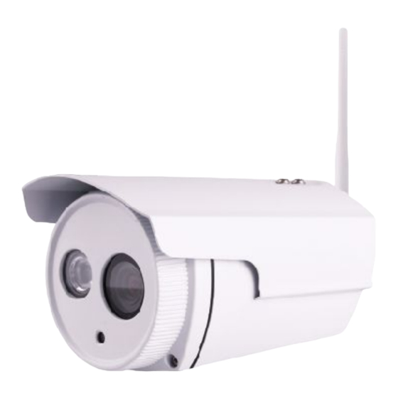
- Page 1 User Manual User Manual Outdoor HD Wireless IP Camera Model: SABIP1200 V1.0...
-
Page 2: Table Of Contents
Table of Contents 1 Overviews................................3 1.1 Key Features..................................3 1.2 Read Before Use................................4 1.3 Packing Contents................................4 1.4 Physical Description................................4 1.5 Hardware Installation................................. 6 2 Accessing the Network Camera........................6 2.1 Hardware Connection & Software Installation....................... 6 2.2 Access the Camera in LAN...............................7 2.2.1 Wired connection................................ - Page 3 4.4.5 Port....................................38 4.4.6 Mail Settings................................40 4.4.7 FTP Settings................................42 4.4.8 P2P....................................43 4.5 Video....................................43 4.5.1 Video Settings................................43 4.5.2 On Screen Display..............................44 4.5.3 Snapshot Settings..............................45 4.5.4 IR LED Schedule...............................45 4.5.5 Lens Distortion Correction............................46 4.6 Alarm....................................46 4.7 Record....................................50 4.7.1 Storage Location...............................
-
Page 4: Overviews
1 Overviews The outdoor HD IP Camera is integrated IP Camera with a color CMOS sensor enabling viewing in High Definition resolution. It combines a high quality digital video camera, with a powerful web server, to bring clear video to your desktop from anywhere on your local network or over the Internet. The IP Camera supports the industry-standard H.264 compression technology, drastically reducing file sizes and conserving valuable network bandwidth. -
Page 5: Read Before Use
1.2 Read Before Use Please first verify that all contents received are complete according to the Package Contents listed below. Before the Network Camera is installed, please carefully read and follow the instructions in the Quick Installation Guide to avoid damage due to faulty assembly and installation. This also ensures the product is used properly as intended. - Page 6 Interface Figure 1.2 1 LAN 10/100M adaptive Ethernet interface. Through this interface, IPCAM can be connected with various network devices, such as hub, router, etc. 2 Power Interface Connect the external power adapter, request for 12V/1A power. 3 Reset button Press and hold on the reset button for 5 seconds.
-
Page 7: Hardware Installation
not eligible for warranty or technical services. 1.5 Hardware Installation 1. Screw the mount on the wall with the 3 screws provided. 2. Install the camera on the mounting bracket with 1 screw to complete installation. Please Note: The tail line’s wall hole must be lower than socket, ensure that the rain will not wet out device through tail line. 2 Accessing the Network Camera 2.1 Hardware Connection &... -
Page 8: Access The Camera In Lan
and paste the IP camera tool file to your computer, or drag it onto your Desktop. Shortcut icon for Windows / Mac OS 2.2 Access the Camera in LAN 2.2.1 Wired connection The camera supports HTTP and HTTPS protocols, you can access the camera in two ways. (1) Http:// LAN IP + Http Port No. -
Page 9: Wireless Connection
2.2.2 Wireless connection Camera support EZLink wireless connection , please refer to the Quick Installation Guide. 2.3 Access the Camera in LAN 2.3.1 Static IP Addresses Users who have static IP addresses do not need to set DDNS service settings for remote access. When you have finished connecting the camera using the LAN IP address and port forwarding, you can access the camera directly from the Internet using the WAN IP address and port number. - Page 10 on the left side of the screen, then uncheck the Obtain IP DHCP. IP Address: Set this in the same subnet as your computer , or keep it as default. Subnet Mask: Keep it as default. Gateway and DNS Server: Set it to the IP address of your router.
- Page 11 Figure 2.9 4. If the UPnP of the router has been enable, you do not need to perform following steps. Otherwise, you need to select one of the following methods to configure port forwarding on your router. For these steps, we will be using the TP-LINK brand wireless router as an example.
-
Page 12: Using The Vlc Player
Input the port and IP address of your camera and click Save. Figure 2.12 Here you have finished the Port Forwarding setup. Figure 2.13 5. Now you can access your IP camera by https://domain name: HTTPS port via the Internet. 2.4 Using the VLC player This camera supports RTSP streaming, here you can view the camera using VLC player. - Page 13 Password: 123 Here I can enter one of the following URLs in the VLC. 1) rtsp://admin:123@192.168.1.11:554/videoMain 2) rtsp:// @192.168.1.11:554/videoMain 3) rtsp://:123@192.168.1.11:554/videoMain 4) rtsp://admin@192.168.1.11:554/videoMain Open the VLC, and go to MediaOpen Network Stream option, then enter the URL into VLC. Figure 2.14...
-
Page 14: Ip Camera Connection To The Server
Figure 2.15 Sometimes you may need to enter the user name and password again. Click OK and you can see the real-time preview. Figure 2.16 Figure 2.17 If you cannot play the video in the VLC player, please check the port mapping. You can read Quick Installation Guide about How to configure port forwarding. -
Page 15: Surveillance Software Gui
3 Surveillance Software GUI Please refer to the section 2.1 if you install the camera for the first time. You can start to learn about software operation after finish quick installation. 3.1 Login Window Figure 3.1 Please check the login window above, it was divided to 4 sections from no. 1 to 4. Section1 Enter the Username and password The default administrator username is admin with no password, please reset the password at first using and... - Page 16 password if both are still set to default. Input the new username and password, click "Modify" to complete the modification. You will now use the new username and password to login the camera in the future. Figure 3.2 After logging in for the first time, you will go to “Setup Wizard”automatically. Here you can set the basic parameters of camera, such as camera name, camera time, wireless settings, IP configuration.
- Page 17 Figure 3.5 Wireless networks: Click “Scan”, find the SSID of your wireless router, select and enter the password. Figure 3.6 IP: Set IP address of the camera. You could choose to obtain an IP automatically or set the IP address according to your needs.
-
Page 18: Surveillance Window
Figure 3.7 NOTE: It needs about 1 minute to connect the camera to your router. 3.2 Surveillance Window Figure 3.8 Section1 Live Video / Settings buttons Path to surveillance window. Click this button and back to the surveillance window... - Page 19 : Path to Administrator Control Panel, Click it, and it will lead to Administrator Control Panel and do advanced settings. Section2 Multi-Device Window The firmware inside the camera supports up to maximum of 9 cameras being monitoring at the same time. You can add other cameras in multi-camera panel.
- Page 20 Auto: Select it and the camera will adjust the infra led (on or off) automatically. Manual: Select it and turn off the infra led manually. Schedule: Select it and the IR led light will be off at the schedule period. If you want to define or change the IR led lights schedule time, please go to Settings→Video→IR LED Schedule page.
- Page 21 6----- Record: Click the icon and the camera start recording, you can see a green dot in the live window. Click again and stop recording. The default storage path is C:\IPCamRecord. You can change the storage path: Go to Settings- >Record-> Storage Location panel. 7------Full Screen Click it to make full-screen, or you can double click the surveillance screen to make full-screen.
-
Page 22: Advanced Camera Settings
NOTE For Mac OS, the plugin cannot support Onscreen Mouse function, so you cannot allow to use it. 4 Advanced Camera Settings Click the button “Settings”, goes to Administrator Control Panel to make advanced camera settings. 4.1 Setup Wizard The way to set it,you could refer to section 3.1. Figure 4.1 4.2 Device Status Device Status contains four columns: Device Information, Device Status, Session Status and Log, it will show... -
Page 23: Device Information
you various information about your camera. 4.2.1 Device Information Figure 4.2 Camera Model: Display the model of the camera. Camera Name: The Device Name is a unique name that you can give to your device to help you identify it. Click Basic Settings and go to Device Name panel where you can change your camera name. -
Page 24: Session Status
4.2.3 Session status Session status will display who and which IP is visiting the camera now. Figure 4.4 4.2.4 Log The log record shows who and which IP address accessed or logout the camera and when. Click the page number and go to the corresponding page to see more logs Fill in one page number, click Go button and go to the corresponding page... -
Page 25: Camera Time
cannot contain special characters. Figure 4.6 4.3.2 Camera Time This section allows you to configure the settings of the internal system clocks for your camera. Figure 4.7 Time Zone: Select the time zone for your region from the drop-down menu. Sync with NTP server: Network Time Protocol will synchronize your camera with an Internet time server. -
Page 26: User Accounts
4.3.3 User Accounts Here you can create users and set privilege, visitor, operator or administrator. The default administrator user accounts are admin with a blank password. Figure 4.8 How to change the password? Firstly, select the account which you want to change the password, then select “Change password”, enter the old password and the new password, lastly click modify to take effect. - Page 27 Figure 4.10 Figure 4.11 Delete: Select the account which you want to delete, then click Delete button to take effect. How to change the username ? Firstly, select the account which you want to change the username, then select “Change username”, enter the new password, lastly click modify to take effect.
- Page 28 Figure 4.12 NOTE: The default administrator account cannot be deleted, but you can add other administrator users. If you want to view multi-surveillance screens on one window, you need to login one camera, and set it as the main device, and do Multi-Device Settings, add other cameras to the first one camera. Before you do multi-cams settings, you need to assign different port such as 81, 82, 83, 84, 85, 86, 87, 88 to the cameras if there is 8 cams installed.
- Page 29 1 Click it, camera model, alias, host and HTTP Port will be filled in the following boxes automatically . 2 Enter the User name and Figure 4.1 3 Click Add to take effect . password of the 2nd camera . Camera Model: Our Company produces two series cameras: MJPEG and H.264.
- Page 30 Back to Surveillance Windows, and click Four Windows option, you will see four cameras you added. Figure 4.3 Figure 4.4 Add cameras in WAN If you want to view all cameras via the internet(remote computer), you will need to add them using DDNS domain name.
- Page 31 Use DDNS domain name and port to login. Make sure each camera you need add could login with DDNS name and port. Figure 4.5 Click Multi-Device Settings. Choose The 2nd Device. Fill in the 2nd camera’s name, DDNS domain name, port number.
- Page 32 NOTE : Here the Host must be entered as the second camera’s DDNS domain name, not its LAN IP. Figure 4.7 Return to video window. You will see all of the cameras accessible through the internet. When you are away from home, you can use the first camera’s DDNS domain name and port to view all the cameras via internet.
-
Page 33: Network
4.4 Network This section will allow you to configure your camera’s IP, PPOE, DDNS, Wireless Settings, UPnP, Port, Mail Settings and FTP Settings. 4.4.1 IP Configuration If you want to set a static IP for the camera, please go to IP Configuration page. Keep the camera in the same subnet of your router or computer. - Page 34 Figure 4.14 Set the same Subnet Mask and gateway of the camera with your PC . There are two DNS servers . You can set any of them . Same with gateway is also OK . Figure 4.15 If you don’t know the DNS server, you can use the same settings as the Default Gateway.
-
Page 35: Wireless Settings
4.4.2 Wireless Settings 4.4.3 DDNS The camera has embedded a unique DDNS domain name when producing, and you can directly use the domain name, you can also use the third party domain name. IPCAM domain name Here take cp4911.myipcamera.org for example. Go to option of DDNS on the Settings->Network panel, you can see the domain name. - Page 36 Manufacturer’s DDNS again , here click this button and start Manufacturer’s DDNS Service. Third Party Domain Name Settings User can also use third part DDNS, such as www.no-ip.com. ,www. 3322.com Here take www.no-ip.com for example : ① Step 1 Go to the website www.no-ip.com to create a free hostname Firstly: Login on www.no-ip.com and click No-IP Free to register.
- Page 37 Figure 4.11 Figure 4.12 Please create the domain name step by step according to instructions on www.no-ip.com Step 2 DO DDNS Service Settings within the Camera Please set DDNS Settings within the camera by hostname, a user name and password you’ve got from www.no-ip.com Take hostname ycxgwp.no-ip.info, user name test, password test2012 for example.
- Page 38 Thirdly, fill test as DDNS user, fill password test2012 as DDNS password, fill ycxgwp.no-ip.info as DDNS domain and server URL, Then click save to make effect. The camera will restart and to take the DDNS settings effective. Fourthly, after the restart, login the camera, and go to option of Device Status on the administrator panel, and check if the DDNS status is successful.
-
Page 39: Upnp
4.3.5 UPnP Figure 4.14 The default UPnP status is closed. You can enable UPnP, then the camera’s software will be configured for port forwarding. Back to the “Device Status” panel, you can see the UPnP status: Figure 4.15 The camera’s software will be configured for port forwarding. There may be issues with your routers security settings, and sometimes may error. - Page 40 Step 1: Open the IP Camera Tool, select the camera you would like to change the port of, right click on the IP address, and click on ”Network Configuration”, this brings up the network configuration box as shown in Figure 4.35 and 4.36.
-
Page 41: Mail Settings
Figure 4.19 NOTE: If the camera cannot be accessed, please make sure the port forwarding is succeed. ONVIF port: By default, the ONVIF port is set to 888. Also, they can be assigned with another port number between 1 and 65535(except 0 and 65534). But make sure they can not be conflict with other existing ports. HTTPS port: The default port is 443. - Page 42 is None. If you use Gmail, Transport Layer Security must be set to TLS or STARTTLS and SMTP Port must be set to 465 or 25 or 587, which port you choose should be decided by which Transport Layer Security you select.
-
Page 43: Ftp Settings
4.4.7 FTP Settings If you want to upload record files and images to your FTP server,you can set FTP Settings. Figure 4.22 Figure 4.23 FTP server: If your FTP server is located on the LAN, you can set. If you have an FTP server which you can access on the internet, you can set. Port: Default is port 21. -
Page 44: P2P
4.4.8 P2P Access the camera by smart phone (Android or iOS operating system),please refer to the Quick Installation Guide. First of all, you need to open the P2P function of the camera at “Settings-->Network-->P2P.” Figure 4.24 4.5 Video This section allows you to configure Video stream settings, On screen display and Snapshot settings. 4.5.1 Video Settings There are two ways to set the stream video settings. -
Page 45: On Screen Display
Figure 4.25 Stream type: There are four types to identify different streams you have set. Resolution: The camera supports multiple types, For example: 720P, VGA. The higher the resolution is, the clearer video will become. But the code flux will become larger too, and it will take up more bandwidth. Bit rate: Generally speaking, the larger the bit rate is, the clearer video will become. -
Page 46: Snapshot Settings
Display Timestamp: There are two options: Yes or NO. Select Yes and you can see the system date on the video, Display Camera Name: There are two options: Yes or NO. Select Yes and you can see the device name on the video. -
Page 47: Lens Distortion Correction
Schedule on the Live Video window, At these schedule time, the IR LED lights will be turned off. Figure 4.28 4.5.5 Lens Distortion Correction On this page you can set the distortion correction. There are three options: Low, Medium, High. Figure 4.29 If you replace the lens, the image has found distortion, uneven and so on, you can modify the Select The Distortion Correction Parameter to calibration images. - Page 48 Figure 4.30 To enable motion detection, follow the steps below: 1 Enable Motion detection Sensitivity---- It supports five modes: Lowest, Lower, Low, Medium and High. The higher the sensitivity, the camera will be more easily alarmed. Select one motion sensitivity. 3 Trigger interval--- The interval time between two motion detections.
- Page 49 Settings first. C Take Snapshot If you select this checkbox, when the motion has been detected, the camera will snap the live view window as a still picture and load it to the FTP. Make sure you have set FTP and set FTP as the storage path in Video->Snapshot settings panel.
- Page 50 Click this button and select all time range Figure 4.33 ② Specify an alarm schedule Click the week day words, the corresponding column will be selected. For example, click TUE, the all column of TUE turns to red, that means during Tuesday whole day, when something moving in the detection area, the camera will alarm.
-
Page 51: Record
7 Click Save button to take effect. When the motion is detected during the detection time in the detection area, the camera will alarm and adopt the corresponding alarm indicators. NOTE: You must set the detection area and detection schedule, or else there is no alarm anywhere and anytime. 4.7 Record 4.7.1 Storage Location On this page you can change the manually recording storage path, the default storage path is... -
Page 52: Record Schedule
Figure 4.38 4.7.4 Record Schedule On this page you can enable schedule record. Figure 4.39 Stream: You can select the main stream or sub stream from the drop-down. You can set the store path of the recording file on the Storage Location page. Click Save button to take effect. -
Page 53: System
Figure 4.40 Enable firewall, If you select Only allow access from these IP addresses and fill in 8 IP addresses at most, only those clients whose IP addresses listed in the Only allow access from these IP addresses can access the Network Camera. -
Page 54: System Upgrade
Figure 4.41 4.9.2 System Upgrade Click Browse, choose the correct bin file( System firmware or Web UI) and then click System upgrade. Don’t shut down the power during upgrade. After upgrading, you can see the upgrade result. Figure 4.16 If you want to verify the firmware version of you camera, please go to Device Status-> Device Information Page to check. -
Page 55: Patch Installation
Figure 4.17 Enter the User name and password . Figure 4.18 CAUTION: If your camera works well with the current firmware, we recommend not upgrading. Please don’t upgrade the firmware unnecessarily. Your camera may be damaged if misconfigured during an upgrade. NOTE: 1) Don’t upgrade the firmware through the web UI in WAN, or else the upgrade may be failed. -
Page 56: Factory Reset
Figure 4.42 4.9.4 Factory Reset Click Factory Reset button and all parameters will return to factory settings if selected. The default administrator username is admin with a blank password. Figure 4.43 4.9.5 Reboot Click Reboot System to reboot the camera. This is similar to unplugging the power to the camera. Figure 4.44... -
Page 57: Appendix
5 Appendix Install the add-on of Firefox browser, Google Chrome and IE Chrome. Figure 6.1 Figure 6.2... - Page 58 Figure 6.3 Figure 6.4...
- Page 59 Figure 6.5 Figure 6.6...
-
Page 60: Uninstall The Add-On Of Firefox Browser, Google Chrome And Ie Chrome
5.1.2 Uninstall the add-on of Firefox browser, Google Chrome and IE Chrome. Figure 6.7... -
Page 61: I Have Forgotten The Administrator Password
Figure 6.8 Figure 6.9 5.1.3 I have forgotten the administrator password To reset the administrator password, you had better unplug the network cable firstly. After that, press and hold down the RESET BUTTON about 5 seconds. Releasing the reset button, the password will turn to the factory default. -
Page 62: Camera Can Not Record
5.1.5 Camera can not record Camera can not record when I click Record button or I can’t change the manually record path When you use Windows7 or Vista, you may be not able to do manually record or change the record path because of the security settings of computer. -
Page 63: Can't Access Ip Camera In Internet
Figure 6.7 NOTE : Make sure that your firewall or anti-virus software does not block the camera or ActiveX. If you could not see video, please shut down firewall or anti-virus software to try again. 5.1.7 Can’t access IP camera in internet There are some reasons: 1 ActiveX controller is not installed correctly 2 The port which camera used is blocked by Firewall or Anti-virus software. -
Page 64: Specification
Default admin username: admin with a blank password 5.3 Specification ITEMS IP Camera Image Sensor Sensor High Definition Color CMOS Sensor Display Resolution 1.0 Megapixels Min. Illumination 0 Lux (With IR Illuminator) Lens Type Glass Lens focal length f:2.8mm,4mm,6mm,8mm,selectable Lens Aperture F1.2 Diagonal angle of view... -
Page 65: Ce & Fcc
Firewall Supports IP Filtering Reset Reset button is available Power Supply DC 12V/1.0A Power Power Consumption 4.2 Watts (Max.) Dimension(mm) 153(L)x 92(W)x 86(H) Physical Net Weight 380g Operating -20°C ~ 60°C (-4°F ~ 131°F) Temperature Operating Humidity 10% ~ 80% non-condensing Environment Storage Temperature -20°C ~ 60°C (-4°F ~ 140°F) - Page 66 This is a Class B product. In a domestic environment, this product may cause radio interference, in which case the user may be required to take adequate measures.
Need help?
Do you have a question about the SABIP1200 and is the answer not in the manual?
Questions and answers