
Subscribe to Our Youtube Channel
Related Manuals for Schwinn 570U


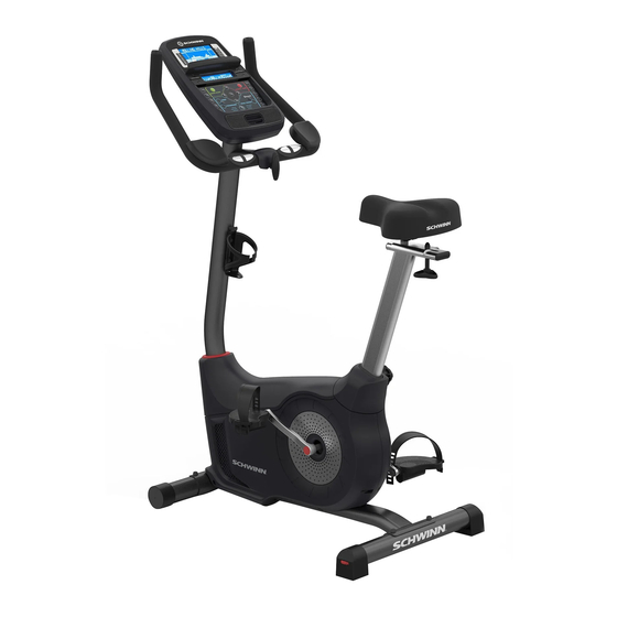
Summary of Contents for Schwinn 570U
- Page 1 This product is compliant with the applicable CE requirements. ASSEMBLY MANUAL / OWNER’S MANUAL...
-
Page 2: Table Of Contents
® indicates trademarks registered in the United States. These marks may be registered in other nations or otherwise protected by common law. Schwinn, the Schwinn Quality logo, Schwinn 570U, Schwinn Connect, Bowflex, Nautilus, and Universal are trademarks owned by or licensed to Nautilus, Inc. -
Page 3: Important Safety Instructions
IMPORTANT SAFETY INSTRUCTIONS This icon means a potentially hazardous situation which, if not avoided, could result in death or serious injury. Obey the following warnings: Read and understand all warnings on this machine. Carefully read and understand the Assembly instructions. •... -
Page 4: Safety Warning Labels / Serial Number
SAFETY WARNING LABELS AND SERIAL NUMBER • Set up and operate this machine on a solid, level, horizontal surface. • Make the Pedals stable before you step on them. Use caution when you step on and off the machine. • Disconnect all power before servicing this machine. • Do not operate this machine outdoors or in moist or wet locations. Keep the foot pedals clean and dry. •... -
Page 5: Specifications
SPECIFICATIONS Maximum User Weight: 136 kg (300 lbs.) Total Surface Area (footprint) of equipment: 5670 cm Machine Weight: 28.5 kg (62.3 lbs.) Power Requirements: Input Voltage: 100 - 240V AC, 50/60Hz, 0.4A Output Voltage: 9VDC, 1.5A Complies with: 141cm (55.6”) I SO 20957 compliant. Connectivity: 105cm (41.3”) 54cm (21.4”) DO NOT dispose of this product as refuse. This product is to be recycled. For proper disposal of this product, please follow the prescribed methods at an approved waste center. -
Page 6: Parts
PARTS 13 (R) 12 (L) Item Qty Description Item Description Main Frame Seat Post Front Stabilizer Adjustment Knob Rear Stabilizer Seat Top Shroud Left Pedal (L) Mast Gasket Right Pedal (R) Console Mast (with Handlebar Mount) Water Bottle Holder Handlebars AC Adapter Console Handlebar Mount Cover... -
Page 7: Hardware
HARDWARE / TOOLS Item Description Button Head Hex Screw M8 x 25 Lock Washer M8 Curved Washer M8 Flat Washer M8 T-handle Note: Select pieces of Hardware have been provided as spares on the Hardware Card. Be aware that there may be remaining Hardware after the proper assembly of your machine. -
Page 8: Assembly
1. Attach Stabilizers to Main Frame Note: Hardware(*) is pre-installed on the stabilizers and not on Hardware Card. Make sure transport wheels on the front stabilizer point forward, and the Schwinn decal on the rear stabilizer faces outward from the machine. - Page 9 3. Install Handlebars on Console Mast NOTICE: Do not crimp the cables. Put the Handlebar (7) in the bracket (6a), adjust the Handlebar to the desired angle, and install the T-handle (E) through the holes. Use the pull cable in the Handlebar Mount to route the HR cable (7a) through the slot (6c) under the Handlebar Mount to the top of the mast.
- Page 10 4. Install Console on Console Mast Note: Remove the pre-installed screws(*) from the back of the Console before you connect the cables. NOTICE: Do not crimp the cables.
- Page 11 5. Install Seat Post on Frame NOTICE: Make sure the Adjustment Knob engages the Seat Post. Do not set the Seat Post position higher than the stop mark (STOP) on the tube. STOP 6. Attach Seat to Seat Post NOTICE: Be sure the Seat is straight. Tighten the nuts (11b) on the Seat bracket (11a) to hold the Seat in position.
- Page 12 7. Install Pedals Note: The Left Pedal is reverse-threaded. Be sure to attach Pedals on the proper side of the Bike. Orientation is based from a seated position on the bike. The Left Pedal has an “L”, the Right Pedal an “R”. 13 (R) 12 (L)
- Page 13 8. Install Water Bottle Holder Note: The hardware(*) is pre-installed on the Console Mast and not on Hardware Card. 9. Connect AC Adapter 10. Final Inspection Inspect your machine to ensure that all hardware is tight and components are properly assembled. Be sure to record the serial number in the field provided at the front of this manual.
-
Page 14: Leveling The Bike
BEFORE YOU START Leveling Your Bike Levelers are found on each side of the Rear Stabilizer. Turn the knob to adjust the stabilizer foot. Make sure the bike is level and stable before you exercise. Moving Your Bike To move the upright bike, carefully tilt the Handlebars toward you while pushing the front of the bike downward. Push the bike to the desired location. -
Page 15: Features
FEATURES Console Water Bottle Holder Handlebars with Elbow Pads MP3 Input Adjustable Seat USB Port Seat Slider Adjustment Knob Contact Heart Rate (CHR) Sensors Seat Post Adjustment Knob Speakers Pedals Stabilizers Media Tray Levelers Telemetry Heart Rate (HR) Receiver Fully Shrouded Flywheel Bluetooth Connectivity (not shown) ®... -
Page 16: Console Features
Console Features The Console provides important information about your workout and lets you control the resistance levels while you exercise. The Console features the Schwinn Dual Track display with touch control buttons to navigate you through the ™ exercise programs. - Page 17 Resistance Level Quick Buttons- Shifts the resistance levels to the setting quickly during a workout Achievement Indicator Lights- when an achievement level is reached or a result is reviewed, the achievement indicator light will activate. Schwinn Dual Track Display ™...
- Page 18 Achievement Display The Achievement Display activates when a workout goal is reached or a workout milestone is surpassed from past workouts. The Console display will congratulate and inform the User of their achievement, along with a celebratory sound. 40% 70% Lower Display Data The Lower Display shows the Workout Values. and can be customized for each User (Consult the “Edit User Profile”...
-
Page 19: Bluetooth ® Connectivity
® ® exported from the fitness machine, connect the USB Flash Drive to a computer and upload the file to your Schwinn Connect™ account. Note: USB Flash Drives must be 16 GB or smaller in size and formatted in FAT32. Do not use a micro-USB drive. -
Page 20: Virtual Reality Experience On Your Fitness Machine
2. Sign in to the Schwinn Connect™ website at www.schwinnconnect.com, or create a new account. To create a new account, click on the “Create New Account” button. 3. Click on the list icon in the upper corner of the web page and select “Upload workout”. -
Page 21: Remote Heart Rate Monitor
Remote Heart Rate Monitor Monitoring your Heart Rate is one of the best procedures to control the intensity of your exercise. Contact Heart Rate (CHR) sensors are installed to send your heart rate signals to the Console. The Console can also read telemetry HR signals from a Heart Rate Chest Strap Transmitter that operates in the 4.5kHz - 5.5kHz range. - Page 22 The graph is a brief guideline, describing the generally suggested target heart rates based on age. As noted above, your optimal target rate may be higher or lower. Consult your physician for your individual target heart rate zone. Note: A s with all exercises and fitness regimens, always use your best judgment when you increase your exercise time or intensity.
-
Page 23: Operations
OPERATIONS What to Wear Wear rubber-soled athletic shoes. You will need the appropriate clothes for exercise that allow you to move freely. How Often Should You Exercise Consult a physician before you start an exercise program. Stop exercising if you feel pain or tightness in your chest, become short of breath, or feel faint. -
Page 24: Quick Start / Manual Program
3. T ime: Push the Increase/Decrease buttons to adjust the currently active value (flashing). Push the Left/Right buttons to change which segment is the currently active value (hour / minute / AM or PM). Push OK to set. 5. U nits of Measurement: Push the Increase/Decrease buttons to adjust between “MILES” (Imperial English) or “KM” (metric). Push OK to set. The Console goes back to the Power-Up / Idle Mode screen. Note: To adjust these selections, consult the “Console Set-Up Mode”... - Page 25 Edit User Profile 1. From the Power-Up Mode screen, push the USER button to select one of the User Profiles. 2. Push the OK button to select the User Profile. 3. The Console display shows the EDIT prompt and the current User Profile name. Push OK to start the Edit User Profile option.
-
Page 26: Profile Programs
3. The Console display shows the current User Profile name and the EDIT prompt. Push the Increase() or Decrease() buttons to change the prompt. Note: To exit the Edit User Profile option, push the PAUSE/END button and the console will go back to the Power-Up Mode screen. 4. The Console display shows the RESET prompt and the current User Profile name. Push OK to start the Reset User Profile option. - Page 27 Pyramids Pyramids Summit Pass Summit Pass CHALLENGES Uphill Finish Cross-Training Uphill Finish Uphill Finish Cross-Training Cross-Training Interval Interval Stairs Interval Stairs Interval Interval Stairs Stairs Workout Profile and Goal Program The Console lets you select the Profile Program and type of Goal for your workout (Distance, Time or Calories), and set the Goal value. 1. Sit on the machine. REVED : 122612 REVED : 122612 2.
- Page 28 Recovery Test Program Recovery Test shows how quickly your heart recovers from an exercise state to a more restful state. Improved recovery is an indicator of increasing fitness. Note: The Console must be able to read the heart rate information from the Contact Heart Rate (CHR) sensors or Heart Rate Monitor (HRM) to work correctly.
-
Page 29: Pausing Or Stopping
HR signal, the Console automatically goes into Sleep Mode. GOAL TRACK Statistics (and Achievements) The statistics from every workout are recorded to a User Profile. The Schwinn Dual Track Console shows the Goal Track workout Statistics on the Lower Display in three channels: ™ TIME (total), DISTANCE (total), and CALORIES (total) - Page 30 TIME (average), DISTANCE (average) / or LEVEL (average) *, and CALORIES (average) * If the Goal Track Statistic is a single workout, LEVEL (average) is displayed. If the Goal Track Statistic is a combination of multiple workouts, DISTANCE (average) is displayed instead of LEVEL (average). To view the GOAL TRACK statistics of a User Profile: 1.
-
Page 31: Console Setup Mode
CONSOLE SETUP MODE The Console Setup Mode lets you input the date and time, set the units of measurement to either English or Metric, change the machine type, control the sound settings ( on/ off), or see maintenance statistics (Error Log and Run Hours – for service technician use only). Hold down the PAUSE/END button and Right button together for 3 seconds while in the Power-Up Mode to go into the Console Setup Mode. -
Page 32: Maintenance
MAINTENANCE Read all maintenance instructions fully before you start any repair work. In some conditions, an assistant is necessary to do the necessary tasks. Equipment must be regularly examined for damage and repairs. The owner is responsible to make sure that regular maintenance is done. - Page 33 Maintenance Parts Console HR Cables Flywheel Console Mast CHR Sensors Brake Assembly Pedals Seat RPM Sensor Crank Arms Seat Post w/ Slider Speed Sensor Magnets (8) Left Shroud Adjustment Knob Servo Motor Power Inlet Seat Post Shroud Drive Belt Right Shroud Water Bottle Holder Drive Pulley Top Shroud...
-
Page 34: Troubleshooting
TROUBLESHOOTING Condition/Problem Things to Check Solution No display/partial display/ Check electrical (wall) Make sure unit is plugged into a functioning wall outlet. unit will not turn on outlet Check connection on Connection should be secure and undamaged. Replace console adapter or connection at unit if either are damaged. Check data cable integrity All wires in cable should be intact. - Page 35 Condition/Problem Things to Check Solution Check magnet position Magnets should be in place on pulley. (requires shroud removal) Check Speed Sensor Speed sensor should be aligned with magnet and connected to (requires shroud removal) data cable. Realign sensor if necessary. Replace if there is any damage to the sensor or the connecting wire.
- Page 36 Nautilus Bowflex Schwinn Universal ® ® ® ® 8011455.030117.B...
Need help?
Do you have a question about the 570U and is the answer not in the manual?
Questions and answers