Table of Contents
Advertisement
Quick Links
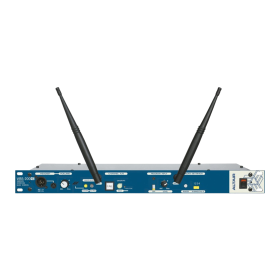
WBS-200
DUAL CHANNEL WIRELESS BASE STATION
WB-200 SERIES INTERCOM SYSTEM
OWNERS MANUAL
EQUIPOS EUROPEOS ELECTRÓNICOS, S.A.L
Avda. de la Industria, 50. 28760 TRES CANTOS-MADRID (SPAIN).
34-91-761 65 80
www.altairaudio.com
AUDIO ELECTRONICS DESIGN
AUDIO ELECTRONICS DESIGN
AUDIO ELECTRONICS DESIGN
AUDIO ELECTRONICS DESIGN
34-91-804 43 58
altair@altairaudio.com
Advertisement
Table of Contents

Related Manuals for Altair WBS-200HD


Summary of Contents for Altair WBS-200HD
- Page 1 DUAL CHANNEL WIRELESS BASE STATION WB-200 SERIES INTERCOM SYSTEM OWNERS MANUAL AUDIO ELECTRONICS DESIGN AUDIO ELECTRONICS DESIGN AUDIO ELECTRONICS DESIGN AUDIO ELECTRONICS DESIGN EQUIPOS EUROPEOS ELECTRÓNICOS, S.A.L Avda. de la Industria, 50. 28760 TRES CANTOS-MADRID (SPAIN). 34-91-761 65 80 34-91-804 43 58 altair@altairaudio.com www.altairaudio.com...
-
Page 2: Table Of Contents
WB-200 SERIES INTERCOM SYSTEM — WBS-200 DUAL CHANNEL WIRELESS BASE STATION 1. INTRODUCTION............................3 2. SWITCHES, CONTROLS, ADJUSTMENTS AND CONNECTORS ..............4 FRONT PANEL............................. 4 REAR PANEL ............................... 5 3. WORKING PRECAUTIONS ........................... 6 4. INSTALLATION ............................6 UNPACKING .............................. 6 MOUNTING.............................. -
Page 3: Introduction
Congratulations on your purchase of the ALTAIR dual channel wireless base station WBS-200 of the WB-200 series wireless intercom system. There is a lot the characteristics that make of the ALTAIR WB-200 series one of the most highlighted in the audio professional market, some are enumerated... -
Page 4: Switches, Controls, Adjustments And Connectors
WB-200 SERIES INTERCOM SYSTEM — WBS-200 DUAL CHANNEL WIRELESS BASE STATION 2. SWITCHES, CONTROLS, ADJUSTMENTS AND CONNECTORS These are the switches, controls, adjustments and connectors that you can find in your ALTAIR wireless intercom base station. The description and explanation of each one will be found in the corresponding section. -
Page 5: Rear Panel
WB-200 SERIES INTERCOM SYSTEM — WBS-200 DUAL CHANNEL WIRELESS BASE STATION REAR PANEL PROGRAM OUTPUT GAIN CONTROL. MAINS CONNECTOR AND FUSEHOLDER. INTERCOM LINE TERMINAL IMPEDANCE ON/OFF. PROGRAM INPUT MIC/LINE SELECTOR SWITCH. INTERCOM LINE CONNECTORS XLR-3-31 AND XLR-3-32. PROGRAM INPUT CONNECTOR XLR-3-31. PROGRAM OUTPUT SELECT: MIC ONLY/PARTY LINE. -
Page 6: Working Precautions
It is always recommended to mount the unit in rack, either for mobile or fixed installations, for protection, safety, aesthetics, etc. The ALTAIR WBS-200 is designed for standard 19" rack mounting, and takes up 1u high rack space. CHANGING THE FUSE This unit incorporates an internal, worldwide voltage operation power supply, and it is prepared to work from 90 to 264 VAC, 50-60Hz. -
Page 7: Connecting To The Mains
WB-200 SERIES INTERCOM SYSTEM — WBS-200 DUAL CHANNEL WIRELESS BASE STATION After extracting the fuse holder, the fuse will appear, take out it and change for the new one. Insert the fuse holder into the mains connector again. Make sure that the fuse is the right one: 2A slow blow type - T2A CAUTION: Always make sure after changing the fuse, that it is the right one. -
Page 8: Program Input Connection
WB-200 SERIES INTERCOM SYSTEM — WBS-200 DUAL CHANNEL WIRELESS BASE STATION PROGRAM INPUT CONNECTION The intercom base station program input signal is carried out through a XLR-3-31 female connector. The input connection is balanced, with a nominal impedance of 40 KΩ (20 KΩ unbalanced). -
Page 9: Balanced Input
WB-200 SERIES INTERCOM SYSTEM — WBS-200 DUAL CHANNEL WIRELESS BASE STATION 2) Using single conductor shielded cable: BALANCED INPUT:... -
Page 10: Pa Output Connection
WB-200 SERIES INTERCOM SYSTEM — WBS-200 DUAL CHANNEL WIRELESS BASE STATION PA OUTPUT CONNECTION The PA output signal is carried out through a XLR-3-32 male connector. The output is balanced, with a nominal impedance of 100 Ω. The next list shows the input pins correspondence as A.E.S recommends: PA OUTPUT - XLR-3-32 PIN 1... - Page 11 WB-200 SERIES INTERCOM SYSTEM — WBS-200 DUAL CHANNEL WIRELESS BASE STATION 2) Using single conductor shielded cable:...
-
Page 12: Balanced Input
WB-200 SERIES INTERCOM SYSTEM — WBS-200 DUAL CHANNEL WIRELESS BASE STATION BALANCED INPUT: EXTERNAL UNITS CONNECTION The external units connection to the master station is carried through twin-lead shielded cable and XLR-3-31/XLR-3- 32 connectors. Each base station channel provides one XLR-3- 31 connector and a XLR-3-32 connector wired internally in parallel mode. -
Page 13: Operation
WB-200 SERIES INTERCOM SYSTEM — WBS-200 DUAL CHANNEL WIRELESS BASE STATION Use high quality cables and minimize its longitude. The DC resistance of a low quality cable or very long affects to the power consumption, the channels crosstalk and the system frequency response. -
Page 14: Headset Connection
WB-200 SERIES INTERCOM SYSTEM — WBS-200 DUAL CHANNEL WIRELESS BASE STATION HEADSET CONNECTION A XLR-4 type connector (XLR-4-32) and a TINY Q-G type connector wired in parallel mode, allows connecting a headset and a microphone to the master station. The headset impedance must be 200 Ω... -
Page 15: Mic On/Off/Push To Talk Switch
WB-200 SERIES INTERCOM SYSTEM — WBS-200 DUAL CHANNEL WIRELESS BASE STATION switch start blinking; if the buzzer its not remote muted (consult remote mute all mics and buzzer switches for more information) an intermittent sound takes place during three seconds, the same as in all the units (wired and wireless beltpacks, desk stations, master stations, etc.), connected to the intercom channel selected. -
Page 16: Radio Register Switch
WB-200 SERIES INTERCOM SYSTEM — WBS-200 DUAL CHANNEL WIRELESS BASE STATION input. Totally to the left the signal decreases in 10 dB and totally to the right the signal increases in 20 dB. Keep in mind that these gains are influenced by the position of the program input MICRO/LINE switch selector (placed at the rear panel), because if this switch is in mode micro, we have 30... -
Page 17: Lines A And B Link Switch
WB-200 SERIES INTERCOM SYSTEM — WBS-200 DUAL CHANNEL WIRELESS BASE STATION With the switch pressed the intercom line terminal impedance is in off mode and with the switch depressed it is in on mode. CAUTION: Never leave the intercom line without terminal impedance, because a bad operation of the units connected to the line would take place. -
Page 18: Special Operations
WB-200 SERIES INTERCOM SYSTEM — WBS-200 DUAL CHANNEL WIRELESS BASE STATION 7. SPECIAL OPERATIONS In order to set-up some of the master station possibilities, the unit must be opened removing the six screws of the unit top cover, and for the input and output transformers placement also the six screws of the unit bottom cover, to solder the transformers. -
Page 19: Changing The Mic Gain
WB-200 SERIES INTERCOM SYSTEM — WBS-200 DUAL CHANNEL WIRELESS BASE STATION Remove the links corresponding to the output transformer LK1 and LK2. Place the output transformer, keeping in mind the position of their pins (seven behind and six forward), and solder it to the main PCB. -
Page 20: Block Diagram
WB-200 SERIES INTERCOM SYSTEM — WBS-200 DUAL CHANNEL WIRELESS BASE STATION 8. BLOCK DIAGRAM... -
Page 21: Technical Specifications
WB-200 SERIES INTERCOM SYSTEM — WBS-200 DUAL CHANNEL WIRELESS BASE STATION 9. TECHNICAL SPECIFICATIONS • 220 Ω AC. IMPEDANCE: • 4700 Ω DC. INTERCOM LINE • NOMINAL/MAXIMUM LEVEL: -10 dBu / +3 dBu. • FREQUENCY RESPONSE: 100 Hz — 10 KHz (-3 dB). •... -
Page 22: Warranty
SERIAL NUMBER ........... AUDIO AUDIO ELECTRONICS DESIGN AUDIO AUDIO ELECTRONICS DESIGN ELECTRONICS DESIGN ELECTRONICS DESIGN EQUIPOS EUROPEOS ELECTRÓNICOS, S.A.L Avda. de la Industria, 50. 28760 TRES CANTOS-MADRID (SPAIN). 34-91-761 65 80 34-91-804 43 58 altair@altairaudio.com www.altairaudio.com...
Need help?
Do you have a question about the WBS-200HD and is the answer not in the manual?
Questions and answers