Advertisement
Quick Links
Quick Installation Guide
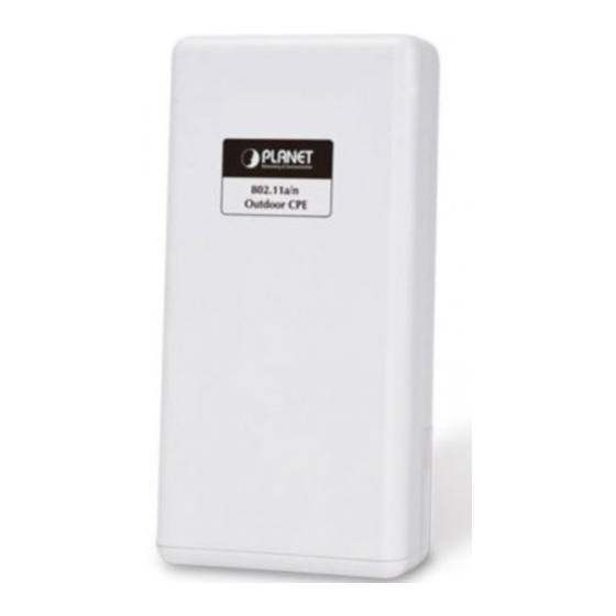
WNAP-7335
300Mbps 802.11a/n Wireless Outdoor CPE
1. Package Contents
Thank you for choosing PLANET WNAP-7335. Before installing the
AP, please verify the contents inside the package box.
WNAP-7335
PoE Injector & Power Cord
If there is any item missing or damaged, please
contact the seller immediately.
Note
3. Physical Introduction
Rear Panel Description – LED Indication
Power LED
LAN 2 LED
Bottom Panel Description – Port
Reset Button
LAN2
Quick Guide
Plastic Strap x 1
– 1 –
LAN 1 LED
Signal Indicator
Grounding Terminal
PoE LAN
RP-SMA
– 3 –
2. Installation Precautions
IMPORTANT SAFETY PRECAUTIONS:
1) LIVES MAY BE AT RISK! Please be aware of the
electrical wires around, and tighten the pole.
Carefully
read
INSTALLATION WARNING" in the manual
before installation.
2) Users MUST use the "PoE Injector" and
"Power Cord" shipped in the box with the
WNAP-7335. Otherwise, the product might be
damaged.
3) Users MUST use a proper and well-installed
Caution
surge arrestor and grounding wired with the
WNAP-7335; otherwise, a sudden lightning could
cause fatal damage to the WNAP-7335. EMD
(Lightning)
UNDER WARRANTY.
4) Users MUST have the antenna connected
first before powering on the WNAP-7335;
otherwise,
might happen.
5) The Antenna is required, and must be purchased
separately.
4. Hardware Installation
STEP 1: (A) Push the latch on the bottom of the WNAP-7335
to remove the sliding cover.
(B) Plug the RJ45 Ethernet cable into the PoE LAN Port and
connect the external antenna to the RP-SMA connectors of
the WNAP-7335. Then, slide back the cover of the
WNAP-7335 to finish the installation.
RP-SMA(Male) to N-male Cable
the
section
"OUTDOOR
DAMAGE
IS
NOT
COVERED
damage
to
the
WNAP-7335
– 2 –
– 4 –
Advertisement

Related Manuals for Planet WNAP-7335


Summary of Contents for Planet WNAP-7335
- Page 1 – 2 – 3. Physical Introduction 4. Hardware Installation Rear Panel Description – LED Indication STEP 1: (A) Push the latch on the bottom of the WNAP-7335 to remove the sliding cover. LAN 1 LED Power LED LAN 2 LED...
- Page 2 AC socket. Then, plug the RJ45 cable (as shown in picture 4 under Step 1) into the POE Connect the WNAP-7335 with your PC via the PoE injector where port of the PoE injector. one end of an Ethernet cable is plugged into the LAN port of the PoE injector while the other end into the LAN port of the PC.
Need help?
Do you have a question about the WNAP-7335 and is the answer not in the manual?
Questions and answers