
Related Manuals for Embedded Artists LPC1343


Summary of Contents for Embedded Artists LPC1343
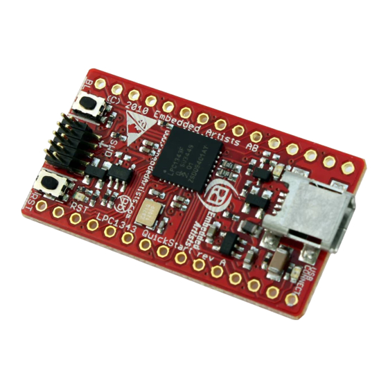
- Page 1 - User’s Guide LPC1343 QuickStart Board Copyright 2013 © Embedded Artists AB LPC1343 QuickStart Board User’s Guide Get Up-and-Running Quickly and Start Developing Your Applications On Day 1! EA2-USG-1002 Rev B...
- Page 2 Embedded Artists AB. Disclaimer Embedded Artists AB makes no representation or warranties with respect to the contents hereof and specifically disclaim any implied warranties or merchantability or fitness for any particular purpose. Information in this publication is subject to change without notice and does not represent a commitment on the part of Embedded Artists AB.
-
Page 3: Table Of Contents
LPC1343 QuickStart Board - User’s Guide Page 3 Table of Contents 1 Document Revision History 2 Introduction Features ESD and Handling Precaution General Handling Care Code Read Protection CE Assessment Other Products from Embedded Artists 2.6.1 Design and Production Services 2.6.2... -
Page 4: Document Revision History
LPC1343 QuickStart Board - User’s Guide Page 4 1 Document Revision History Revision Date Description 2010-10-25 First draft. 2010-10-27 Updated section 3.6. 2012-01-13 Added note about CE marking. Removed schematic from document. 2013-04-22 Updated 5.1 with note about requirement to power the board... -
Page 5: Introduction
LPC1343 QuickStart Board - User’s Guide Page 5 2 Introduction Thank you for buying Embedded Artists’ LPC1343 QuickStart Board based on NXP’s LPC1343 ARM Cortex-M3 microcontroller. This document is a User’s Guide that describes the LPC1343 QuickStart Board hardware design. -
Page 6: General Handling Care
EMC emission limits are not exceeded when connecting other devices to the general expansion connectors of the LPC1343 QuickStart Board. Due to the nature of the LPC1343 QuickStart Board – an evaluation board not for integration into an end-product – fast transient immunity tests and conducted radio-frequency immunity tests have not been executed. -
Page 7: Oem / Education / Quickstart Boards And Kits
Page 7 2.6.2 OEM / Education / QuickStart Boards and Kits Visit Embedded Artists’ home page, www.EmbeddedArtists.com, for information about other OEM / Education / QuickStart boards / kits or contact your local distributor. Copyright 2013 © Embedded Artists AB... -
Page 8: Schematic
The board is powered either via the USB interface or from an external +5V supply. U2 is an on-board voltage regulator capable of creating a +3.3V voltage for the LPC1343. It can deliver up to 150 mA. The LPC1343 itself does not consume that much so there is at least 100mA available for external circuit use. -
Page 9: Bootload Enable Push-Button
Bootload Enable Push-button The LPC1343 sample the state of the PIO0_1 pin immediately after a reset. If the pin is low, the ISP mode is activated and further the pin PIO0_3 is sampled. If high, USB-ISP mode is activated and if low, UARTR-ISP mode is activated. -
Page 10: Expansion Connectors
There are two expansion connectors, J1 and J2. They both have 15 positions and are placed at the board edges. See Figure 2 on page 13 for details about J1 and J2 placement on the board. All programmable pins of the LPC1343 are available on the expansion connectors; see the table below for details. -
Page 11: Usage Of Mcu Pins
LPC1343 QuickStart Board - User’s Guide Page 11 The picture below shows how the LPC1343 QuickStart Board looks on the bottom side. The pinning of the expansion connectors is printed on the bottom side in order to simplify usage of the board. - Page 12 LPC1343 QuickStart Board - User’s Guide Page 12 E2PROM. This pin must have I2C-SDA functionality. PIO0_6 J2-3 Connected to control USB Device connect functionality (attaching a 1.5Kohm resistor to DUB-DP signal). Is USB is not used this pin can be used for other purpose.
-
Page 13: Physical Design
LPC1343 QuickStart Board - User’s Guide Page 13 4 Physical Design This chapter contains information about the physical design of the LPC1343 QuickStart Board. Main Components Figure 2 below illustrates where the main components in the design can be found on the board. -
Page 14: Mechanical Dimensions
700 mil, which simplifies prototyping work with the board. 22 mm 700 mil/17.78 mm 1 mm 2 mm 100 mil/2.54 mm 40 mm pitch on both sides 2.5 mm 1.8 mm 2.0 mm Figure 3 – LPC1343 QuickStart Board Mechanical Dimensions Copyright 2013 © Embedded Artists AB... -
Page 15: Getting Started
SWD interface of the LPC1343 QuickStart Board. Note the orientation of the SWD cable in the LPC1343 end. Pin 1 of the SWD connector (J4) is at the board edge, see picture below. This is because the orientation of the SWD/JTAG connector on the LPC-LINK board. -
Page 16: Activate Lpc1343 Isp Mode
The sequence of steps can be done quickly. The minimum time between step 2 and 3 is in the region of 200mS (which is the reset pulse minimum time from U3 plus the time until the LPC1343 samples the PIO0_1 pin). - Page 17 4 above to the CRP DISABLD drive. 8. Reset the board (SW1 push-button) and the (just downloaded) application will start executing. For details, see LPC1343 User’s Manual [2] from NXP as well as AN10986 [4] (application note from NXP).
- Page 18 LPC1343 QuickStart Board - User’s Guide Page 18 Figure 6 – LPCXpresso IDE Create a Binary File Copyright 2013 © Embedded Artists AB...
- Page 19 LPC1343 QuickStart Board - User’s Guide Page 19 Figure 7 – LPCXpresso IDE Open Command Prompt Figure 8 – Mass Storage Device Copyright 2013 © Embedded Artists AB...
-
Page 20: Further Information
LPC1343 QuickStart Board - User’s Guide Page 20 6 Further Information The LPC1343 microcontroller is a complex circuit and there are a number of other documents with more information. The following documents are recommended as a complement to this document. NXP LPC1343 Datasheet http://ics.nxp.com/products/lpc1000/datasheet/lpc1311.lpc1313.lpc1342.lpc1343.pdf...
Need help?
Do you have a question about the LPC1343 and is the answer not in the manual?
Questions and answers