
Related Manuals for Embedded Artists LPC2478


Summary of Contents for Embedded Artists LPC2478
- Page 1 - User‟s Guide LPC2478 Developer’s Kit Copyright 2011 © Embedded Artists AB LPC2478 Developer’s Kit User’s Guide Get Up-and-Running Quickly and Start Developing Your Applications On Day 1! EA2-USG-0801 Rev I...
- Page 2 Embedded Artists AB. Disclaimer Embedded Artists AB makes no representation or warranties with respect to the contents hereof and specifically disclaim any implied warranties or merchantability or fitness for any particular purpose. Information in this publication is subject to change without notice and does not represent a commitment on the part of Embedded Artists AB.
-
Page 3: Table Of Contents
Reset Generation 3.1.8 I2C E2PROM 3.1.9 Expansion Connectors Memory Layout Usage of CPU Pins LPC2478 OEM Board Mechanical Dimensions and Connector Known Limitation of LPC2478 OEM Board 3.5.1 Ver 1.0 – SDRAM Clock Frequency 3.5.2 Ver 1.0 – Ethernet Clock 3.5.3 NAND FLASH Bad Block 3.5.4... - Page 4 LPC2478 Developer’s Kit - User’s Guide Page 4 Demo Applications 5.1.1 Custom Slideshow Demo Application #3 Initial Setup and Powering Getting Started with uClinux 5.3.1 Basic Requirements 5.3.2 LAN/Ethernet Setup FTDI USB Driver Installation 5.4.1 USB Driver Behavior 6 Further Information...
-
Page 5: Document Revision History
LPC2478 Developer’s Kit - User’s Guide Page 5 1 Document Revision History Revision Date Description 2007-2010 Earlier versions of document. 2010-12-10 Updated manual according to new template. Removed schematics from document. Added known issue with newer SD/MMC memory cards (requiring pull-up resistors). -
Page 6: Introduction
Thank you for buying Embedded Artists‟ LPC2478 Developer’s Kit based on NXP‟s ARM7TDMI-S LPC2478 microcontroller. This document is a User‟s Guide that describes the LPC2478 OEM Board (both 16- and 32-bit data bus versions) and the QVGA Base Board hardware design. It is the User‟s Manual for both the LPC2478 Developer’s Kit as well as for just the LPC2478 OEM Board. -
Page 7: Esd Precaution
ESD. Never touch directly on the LPC2478 OEM Board and in general as little as possible on the QVGA Base Board. The push-buttons on the QVGA Base Board have grounded shields to minimize the effect of ESD. -
Page 8: Code Read Protection
LPC2478 Developers Kit. Due to the nature of the LPC2478 Developers Kit – an evaluation board not for integration into an end- product – fast transient immunity tests and conducted radio-frequency immunity tests have not been executed. -
Page 9: Oem / Education / Quickstart Boards And Kits
Page 9 2.6.2 OEM / Education / QuickStart Boards and Kits Visit Embedded Artists‟ home page, www.EmbeddedArtists.com, for information about other OEM / Education / QuickStart boards / kits or contact your local distributor. Copyright 2011 © Embedded Artists AB... -
Page 10: Lpc2478 Oem Board Design
DP83848 external Ethernet PHY from National is used and interfaces the LPC2478 via the RMII interface. The PHY is driven by an external 50 MHz clock that is also feed to the LPC2478. This is part of the RMII interface specification. -
Page 11: External Memories
3.1.6 External Memory Interface The LPC2478 memory interface is available on the expansion connector. The data bus width is either 16- or 32-bits on the external interface (depending on board version). All signals are buffered. The buffers are disabled unless enabled by external signals. -
Page 12: Expansion Connectors
Both address and data busses are buffered. Usage of CPU Pins Almost all pins of the LPC2478 are directly available on the expansion connectors. Only in a few cases are pins used for dedicated functionality like Ethernet interface and chip select signals. Such pins are not available on the expansion connector. -
Page 13: Lpc2478 Oem Board Mechanical Dimensions And Connector
Yes. Note that VDDA is The QVGA Base Board illustrates how to typically connect external interfaces (like Ethernet, USB, external memory devices, etc) to the LPC2478 OEM Board. Study this schematic (also found in this document) for details. LPC2478 OEM Board Mechanical Dimensions and Connector Figure 1 below contains a drawing of the board that includes mechanical measures. -
Page 14: Known Limitation Of Lpc2478 Oem Board
72 MHz. The limitation results in a maximum cpu clock frequency of 48 MHz when using the external SDRAM. If the SDRAM is not used, the cpu core frequency can be up to full specification of the LPC2478. 3.5.2 Ver 1.0 – Ethernet Clock Due to an error in clock routing between the Ethernet PHY and the LPC2478, rev 1.0 boards have... -
Page 15: Brand Of Memory Chips
SDRAM. The lifetime of memory chips is limited and availability can also be limited from time to time. Embedded Artists make every effort to mount the original design chip on the board. In case that is impossible a compatible chip will instead be mounted without any prior notice. There can be small programming differences between mounted brands. -
Page 16: Qvga Base Board Design
Board. Usage of CPU Pins Almost all pins of the LPC2478 are directly available on the expansion connectors. Only in a few cases are pins used for dedicated functionality like Ethernet interface and chip select signals. Such pins are not available on the expansion connector. The table below lists all pins and their possible restrictions. - Page 17 LPC2478 Developer’s Kit - User’s Guide Page 17 P0.24 Can be connected to accelerometer, Y-axis P0.25 Can be connected to accelerometer, Z-axis, or analog input (trimpot) P0.26 Connects to speaker output on AOUT signal P0.27 I2C-SDA0, connects to PCA9532 (IO expander) P0.28...
- Page 18 LPC2478 Developer’s Kit - User’s Guide Page 18 P2.3 LCDFP signal, vsync for QVGA display. Also connects to ETM pads, if connector mounted. P2.4 LCDENAB signal, data enable for QVGA display. Also connects to ETM pads, if connector mounted. P2.5 LCDLP signal, hsync for QVGA display.
-
Page 19: Known Limitation Of Qvga Base Board
LPC2478 Developer’s Kit - User’s Guide Page 19 P3.22 Can be connected to RS232 interface (if 16-bit databus version used) P3.23 No special usage on QVGA Base Board (if 16-bit databus version used) P3.24 No special usage on QVGA Base Board (if 16-bit databus version used) P3.25... -
Page 20: Jumpers
The QVGA Base Board has a number of jumpers in order to be able to connect/disconnect and fully utilize all functionality of the LPC2478 and the boards. Figure 3 illustrates all jumpers and explains to what part of the design they belong. -
Page 21: Default Jumper Positions
LCD interface since signals (P1.27-P1.29) are also connected to the ISP1301. When using the 32-bit data bus version of the LPC2478 OEM Board, all jumpers in connectors J20 should always be removed. Also J23/J24 should not be in upper position. The UART signals (in signals P3.xx) else collide with the upper 16 data bits of the data bus. -
Page 22: Connectors
LPC2478 Developer’s Kit - User’s Guide Page 22 Connectors Figure 5 illustrate the position of all external connectors on the QVGA Base Board. Input power USB-to-serial USB OTG/Device USB Host Ethernet SD/MMC JTAG not mounted Expansion connector Expansion J1+J2 connector... -
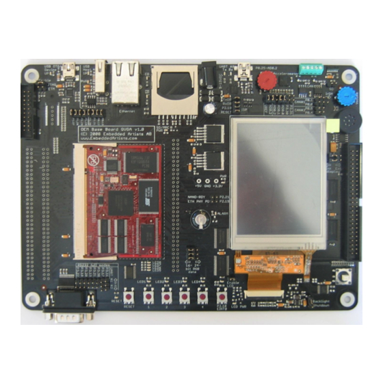
Page 23: Important Components
LPC2478 Developer’s Kit - User’s Guide Page 23 Important Components Figure 6 below illustrates the position on the QVGA Base Board for some important components in the design. IrDA Accelerometer transceiver USB-to-serial Trimpot for SD/MMC LEDs activity LEDs analog input... -
Page 24: Getting Started
LPC2478 Developer’s Kit - User’s Guide Page 24 5 Getting Started This chapter contains information about how to get acquainted with the LPC2478 Developer’s Kit. Please read this section first before you start using the board - it will be well spent time! Demo Applications demonstrate the different features of the The board is pre-loaded with 12 demo applications. - Page 25 LPC2478 Developer’s Kit - User’s Guide Page 25 Below is a sample text file for defining a slide show. It demonstrates how a typical slide show presentation is created. # Short sequence of images clear load /slideshow/test/05.jpg 0 show 0 none load /slideshow/test/29.jpg 1...
- Page 26 LPC2478 Developer’s Kit - User’s Guide Page 26 This example assumes it takes 250ms to load an image. By placing the load commands before the wait command the load times will be deducted from the delay. label a load myimg0.gif 0 load myimg1.gif 1...
- Page 27 The QVGA Base Board contains an USB-to-Serial bridge chip (FT232R from FTDI) that connects UART channel #0 on the LPC2478 to a virtual COM port on the PC (via USB). It is this serial channel that is the console interface to system (in the uClinux system, this is the console, and in the sample applications this is the interface where printf() ends up in).
- Page 28 There is a uClinux port for the board. In order to get started, the system has to be prepared for running uClinux. The first step is to download the uBoot bootloader into the LPC2478 internal flash memory. This can be downloaded either via ISP or via the JTAG interface. The uBoot bootloader hex file can be downloaded from the board‟s support page.
- Page 29 An IP address starting with 192.168.0.x is a common IP subnet for many PCs. If this does not match your PC either change the IP address of your PC or change the IP address of the LPC2478 OEM Board (see description of this at the last section of this page).
- Page 30 LPC2478 Developer’s Kit - User’s Guide Page 30 Note the green LEDs (on the Ethernet connector of the QVGA Base Board) that flash every time an Ethernet frame is received. You should be able to see the LED flash at the same rate as the ping packages are sent.
- Page 31 LPC2478 Developer’s Kit - User’s Guide Page 31 Ports Figure 11 – Device Manager Dialog The new COM port (USB Serial Port) will be listed under the Ports list. Right-click on the new USB Serial Port and select Properties, as illustrated in Figure 12 below.
- Page 32 LPC2478 Developer’s Kit - User’s Guide Page 32 can use different baudrate settings for the serial channel. Other baudrates can also be used, depending on your specific application. UART settings Advanced settings Figure 13 – USB Serial Port Properties Dialog Set the desired COM port number under the Advanced settings dialog.
- Page 33 LPC2478 Developer’s Kit - User’s Guide Page 33 A message like below should be printed on the terminal. Please note that the picture below is just an example of the uClinux startup console. Figure 15 – Example Terminal Window, Startup Message from uClinux Console 5.4.1...
- Page 34 LPC2478 Developer’s Kit - User’s Guide Page 34 6 Further Information The LPC2478 microcontroller is a complex circuit and there exist a number of other documents with a lot more information. The following documents are recommended as a complement to this document. NXP LPC2478 Datasheet http://ics.nxp.com/products/lpc2000/datasheet/lpc2478.pdf...
- Page 35 Development Boards & Kits - ARM Click to view products by manufacturer: Embedded Artists Other Similar products are found below : CWH-CTP-VSPA-YE CY4541 EVAL-ADUCM320IQSPZ FRDM-KV31F POLYPOD-BGA324 POLYPOD-TQ144 POLYPOD-TQ176 KEA128LEDLIGHTRD KIT_XMC42_EE1_001 SAFETI-HSK-RM48 LS1024A-RDB ADM00573 FRDM-KL28Z PICOHOBBITFL MCIMX53-START-R TWR-K65F180M KEA128BLDCRD CC-ACC-MMK-2443 STM8L1528-EVAL YSPKS5D9E10 YGRPEACHFULL...
Need help?
Do you have a question about the LPC2478 and is the answer not in the manual?
Questions and answers