
Related Manuals for Embedded Artists iMX RT1062


Summary of Contents for Embedded Artists iMX RT1062
- Page 1 - User’s Guide iMX RT1062 Developer’s Kit Copyright 2019 © Embedded Artists AB iMX RT1062 Developer’s Kit User’s Guide Get Up-and-Running Quickly and Start Developing Your Application On Day 1! Arrow.com. Downloaded from...
- Page 2 Embedded Artists AB. Disclaimer Embedded Artists AB makes no representation or warranties with respect to the contents hereof and specifically disclaim any implied warranties or merchantability or fitness for any particular purpose. Information in this publication is subject to change without notice and does not represent a commitment on the part of Embedded Artists AB.
-
Page 3: Table Of Contents
RT1062 OEM Developer’s Kit - User’s Guide Page 3 Table of Contents 1 Document Revision History 2 Getting Started iMX RT1062 Developer's Kit Content Hardware Overview Connecting - Get Started 2.3.1 Tera Term Terminal Emulation Application 2.3.2 PuTTY terminal emulation application... - Page 4 RT1062 OEM Developer’s Kit - User’s Guide Page 4 4.18.2 SDIO interface connected to both SD memory card and M.2 connector 4.18.3 Do not use DQS pin (SEMC_DQS) 5 Troubleshooting No SWD/JTAG Connection Powering Contact with OEM Board MCU...
-
Page 5: Document Revision History
RT1062 OEM Developer’s Kit - User’s Guide Page 5 1 Document Revision History Revision Date Description 2019-02-07 First released version. 2019-12-02 Added information about Ethernet reset and interrupt signals connected to JTAG_TDI and JTAG_TDO, respectively. Copyright 2019 © Embedded Artists AB Arrow.com. -
Page 6: Getting Started
Please read this chapter first before you start using the board - it will be well spent time! First of all, thank you for buying Embedded Artists’ iMX RT1062 Developer’s Kit based on NXP’s ARM Cortex-M7 i.MX RT1062 microcontroller. You will get up-and-running quickly! ... - Page 7 4. ON/OFF push-button - a 5 second press will shut down the main 3.3V supply. 5. ISP Enable push-button - pressing this button while the board power up will place the i.MX RT1062 is ISP mode (typically used for programming the iMX RT1062 OEM board flash memory).
-
Page 8: Connecting - Get Started
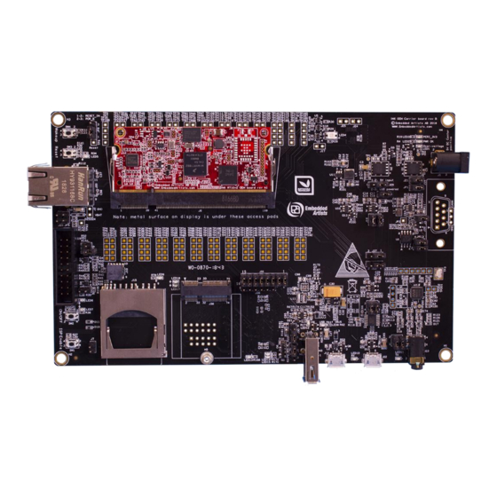
RT1062 OEM Developer’s Kit - User’s Guide Page 8 Figure 2 – iMX RT1062 Developer's Kit Bottom View Connecting - Get Started Begin by connecting the micro-B USB connector to position 1) in Figure 1 above. Connect the other end of the USB cable to the PC. -
Page 9: Tera Term Terminal Emulation Application
RT1062 OEM Developer’s Kit - User’s Guide Page 9 recommend using any of the two alternative terminal applications presented in the following sub- sections. 2.3.1 Tera Term Terminal Emulation Application We recommend that you use Tera Term which can be downloaded and installed from either of the links below. -
Page 10: Putty Terminal Emulation Application
RT1062 OEM Developer’s Kit - User’s Guide Page 10 Figure 6 – Tera Term Menu 2.3.2 PuTTY terminal emulation application Alternatively you can use PuTTY. It is another commonly used terminal emulation application. PuTTY can be downloaded and installed from the link below. -
Page 11: Alternative Powering
ESD. Never touch directly on the iMX RT1062 OEM Board and in general as little as possible on the iMX OEM Carrier Board. The push-buttons on the iMX OEM Carrier Board have grounded shields to minimize the effect of ESD. -
Page 12: General Handling Care
Page 12 General Handling Care Handle the iMX RT1062 OEM Board and iMX OEM Carrier Board with care. The boards are not mounted in a protective case/box and are not designed for rough physical handling. Connectors can wear out after excessive use. The iMX OEM Carrier Board is designed for prototyping use, and not for integration into an end-product. -
Page 13: Otp Fuse Programming
RT1062 Developers Kit. Due to the nature of the iMX RT1062 Developers Kit – an evaluation board not for integration into an end-product – fast transient immunity tests and conducted radio-frequency immunity tests have not been executed. -
Page 14: Demo Application
Page 14 3 Demo Application The iMX RT1062 Developer's Kit comes pre-loaded with a demo application. If the demo application is missing or over-written by another application, follow the guidelines for how to download a program in the document iMX RT1062 Developer's Kit Program Development Guide. A pre-compiled binary file is available on the support site. -
Page 15: Imx Oem Carrier Board Design
RT1062 OEM Developer’s Kit - User’s Guide Page 15 4 iMX OEM Carrier Board Design This chapter contains information about the peripherals and general design of the iMX OEM Carrier Board and how to set the different jumpers on the board. The schematic can be downloaded in pdf format from the support page, and is recommended to have printed out while reading this chapter. -
Page 16: Sp2A: Power Supplies
RT1062 OEM Developer’s Kit - User’s Guide Page 16 SP2a: Power Supplies The power supply structure on the iMX OEM Carrier board is straight forward. There are two powering sources, selected via J29: 1. +5V DC via power jack (J1). 2.1mm inner diameter, 5.5mm outer diameter, center pin positive. - Page 17 Page 17 There are two voltage regulators: 3.3V/2A that is the main supply voltage for both the iMX RT1062 OEM board and the iMX OEM Carrier board. This is a buck dcdc regulator to minimize power dissipation. The regulator can be switched on/off by control signal EXT_PWR_EN.
-
Page 18: Sp2B: Current Measurement
Figure 13 – Location of Current Measurement Connectors J3 and J4 Note that the main 3.3V supply powers both the iMX RT1062 OEM board and peripherals on the iMX OEM Carrier board, like LCD, SD interface, Audio codec, CAN interface, LEDs, etc. For better discrimination and resolution of current measurement, it is possible to measure currents on the iMX RT1062 OEM board also. -
Page 19: Sp2C: Vbat Powering
RT1062 OEM Developer’s Kit - User’s Guide Page 19 J6 allows measuring the internal 1.8V supply to the EcoXiP flash by measuring the voltage drop over a 20 milliohm resistor. J6 - 1.8V EcoXiP current J2 - VDD_SOC_ON current... -
Page 20: Sp3-Sp4: Oem Board Connector (Sodimm) And Access Pads
SP3-SP4: OEM Board Connector (SODIMM) and Access Pads The iMX RT1062 OEM board connector is a standard DDR2 SO-DIMM socket with 200 positions and 0.6mm pitch. It has 1.8V keying (which is what DDR2 stands for). The JEDEC standard defining the DDR2 SODIMM boards is called JEDEC MO-224. -
Page 21: Sp5: Push-Buttons And Leds
RT1062 OEM Developer’s Kit - User’s Guide Page 21 SP5: Push-buttons and LEDs There are four push-buttons, as presented in the picture below. The reset push-button, SW3, can be configured to control one of two different signals via JP8. - Page 22 RT1062 OEM Developer’s Kit - User’s Guide Page 22 There is also jumper to allow a specific signal (GPIO_B1_13) to control the watchdog input signal, WDOG_B. This jumper is inserted by default. Watchdog Control J9 inserted by default Figure 18 –Location of Watchdog Control Jumper, J9 Copyright 2019 ©...
-
Page 23: Sp6: Debug Interfaces
RT1062 OEM Developer’s Kit - User’s Guide Page 23 SP6: Debug Interfaces There are two debug interface connectors available: J10 – this is a Cortex Debug connector. It is a 2x5 pos, 50 mil pitch connector without a shroud. - Page 24 RT1062 OEM Developer’s Kit - User’s Guide Page 24 Note about SWO trace: Note that the i.MX RT1062 MCU does not connect the SWO trace output signal on JTAG_TDO, which would be the normal (since JTAG_TDO connect to the Cortex debug connector where SWO in defined to be connected).
-
Page 25: Sp7: Usb Interfaces
RT1062 OEM Developer’s Kit - User’s Guide Page 25 SP7: USB Interfaces The iMX OEM Carrier board has two USB interfaces, one USB Host and one USB OTG: The USB Host interface has a USB-A connector, J13. By default this interface has VBUS power enable always on. -
Page 26: Sp8: Can
RT1062 OEM Developer’s Kit - User’s Guide Page 26 SP8: CAN There is one CAN interface on the board. It is connected to FLEXCAN2 and CANFD of the i.MX RT1062 (these two peripherals share the same pins vis pin multiplexing - only one can be active at the same time). -
Page 27: Sp9: Sdio Bus And Sd Memory Card Interface
RT1062 OEM Developer’s Kit - User’s Guide Page 27 4.10 SP9: SDIO Bus and SD Memory Card Interface There is a SD memory card interface with SD card connector J15. The associated power switch is controlled by GPIO_AD_B0_05. By default this signal is active high (high = power to SD card) but can optionally be changed to active low SJ3 in 2-3 position. -
Page 28: Sp10: Lcd Interface
RT1062 OEM Developer’s Kit - User’s Guide Page 28 Due to signal integrity of the high-speed signals, three signals are not available per default at the TPx access pads described in section 4.5 . The stubs to the access pads are removed from the tracks by not having R150, R151 and R152 not mounted. -
Page 29: Sp12: Uart-To-Usb Bridge
RT1062 OEM Developer’s Kit - User’s Guide Page 29 4.13 SP12: UART-to-USB Bridge The UART-to-USB bridge chip (FT230XS-R from FTDI) on the iMX OEM Carrier Board connects to UART channel #1 on the i.MX RT1062. It exist to simplify connection to a PC because serial ports are not so common any more, especially not on laptops. -
Page 30: Sp13: Audio Codec
RT1062 OEM Developer’s Kit - User’s Guide Page 30 4.14 SP13: Audio Codec The board contains an audio codec based on WM8960. The codec is controlled via I2C and audio data is transferred over the SAI bus with the I2S format. -
Page 31: Sp14-Sp17: M.2 Power Supply And Control
RT1062 OEM Developer’s Kit - User’s Guide Page 31 4.15 SP14-SP17: M.2 Power Supply and Control The M.2 interface is implemented over several schematic pages. The picture below illustrates the main components, connectors and jumper settings for the interface. -
Page 32: Sp14: M.2 Power Supply And Control
RT1062 OEM Developer’s Kit - User’s Guide Page 32 It is possible to disconnect the SD memory card connector, J15, from the SDIO bus by removing isolation resistors R86-R91. This is typically not needed except when running the M.2 interface at very high SDIO bus frequencies. R86-R91 are found on the bottom side under the LCD. -
Page 33: Sp17: M.2 (Ngff) E-Key Connector
RT1062 OEM Developer’s Kit - User’s Guide Page 33 The M.2 audio interface typically comes from a Bluetooth interface. With the help of the multiplexors, the audio data can be directed to the i.MX RT or the audio codec. -
Page 34: Usage Of Cpu Pins
RT1062 OEM Developer’s Kit - User’s Guide Page 34 4.17 Usage of CPU Pins Almost all pins of the i.MX RT1062 MCU are directly available on the SODIMM expansion connector. In a few cases are pins used for dedicated functionality like the Ethernet interface, EcoXiP interface and on-board SDRAM. - Page 35 RT1062 OEM Developer’s Kit - User’s Guide Page 35 GPIO_AD_B0_14- GPIO_AD_B0_14 Connects to TD on CAN transceiver FLEXCAN2_TX GPIO_AD_B0_12- GPIO_AD_B0_12 Connects to UART-to-USB bridge (U1_TXD). LPUART1_TX GPIO_AD_B0_13- GPIO_AD_B0_13 Connects to UART-to-USB bridge (U1_RXD). LPUART1_RX GPIO_AD_B1_10- GPIO_AD_B1_10 Connects to M.2 interface as WL_DEV_WAKE.
- Page 36 RT1062 OEM Developer’s Kit - User’s Guide Page 36 GPIO_B0_10-BOOT_CFG1[6]- GPIO_B0_10 Parallel RGB LCD interface - Green3 bit LCDIF_D6 GPIO_B0_11-BOOT_CFG1[7]- GPIO_B0_11 Parallel RGB LCD interface - Green4 bit LCDIF_D7 GPIO_B0_12-BOOT_CFG2[0]- GPIO_B0_12 Parallel RGB LCD interface - Green5 bit LCDIF_D8...
-
Page 37: Things To Note
CCM_CLK1_P/_N No special usage on iMX OEM Carrier Board. 4.18 Things to Note This section lists things to note when using the iMX RT1062 Developer's Kit. 4.18.1 Three signals in the SDIO interface not available at TPx access pads Due to signal integrity of the high-speed signals, three signals are not available per default at the TPx access pads described in section 4.5 . - Page 38 The third step is to run the just downloaded demo application. There are many tests that can be performed, one after one, to verify correct operation of individual parts of the iMX RT1062 OEM Board as well as the iMX OEM Carrier Board. While doing these tests, be sure to not have any interfering circuits connected to the access pads.
- Page 39 If any part of this document refers to any third party products or services it shall not be deemed a license grant by Embedded Artists for the use of such third party products or services, or any intellectual property contained therein or considered as a warranty covering the use in any manner whatsoever of such third party products or services or any intellectual property contained therein.
- Page 40 RT1062 OEM Developer’s Kit - User’s Guide Page 40 for the Embedded Artists’ product or service described herein and shall not create or extend in any manner whatsoever, any liability of Embedded Artists. This document as well as the item(s) described herein may be subject to export control regulations.
Need help?
Do you have a question about the iMX RT1062 and is the answer not in the manual?
Questions and answers