Table of Contents
Advertisement
Quick Links
Advertisement
Table of Contents

Related Manuals for Powersmart DB7004


Summary of Contents for Powersmart DB7004
- Page 1 INSTRUCTION MANUAL 24-inch Single Stage Gas Snow Thrower Model # DB7004 Have product questions or need technical support? Please feel free to contact us! Website: www.Amerisuninc.com www.powersmartusa.com Toll free: 1-800-791-9458 Mon-Fri 9-5 EST Email: support@amerisuninc.com...
-
Page 3: Table Of Contents
Storage & Cleaning…………...…………………………………………. Troubleshooting…………………………………………………………. Exploded view and parts list……………………………………………... 20 Two (2) years limited warranty……………………...…………………… 30 TECHNICAL DATA 24 inch Single Stage Snow Thrower Model #: DB7004 Engine: 196cc Engine Engine oil Capacity: 20 fl.oz Fuel Tank Capacity: 0.66 Gallon... -
Page 4: Introduction
INTRODUCTION ® Thank You for Purchasing a PowerSmart Product. This manual provides information regarding the safe operation and maintenance of this product. Every effort has been made to ensure the accuracy of the ® information in this manual. PowerSmart reserves the right to change this product and specifications at any time without prior notice. - Page 5 TRAINING Read, understand, and follow all instructions on the machine and in the manual(s) before attempting to assemble and operate. Keep this manual in a safe place for future and regular reference. • Be familiar with all controls and their proper operation. Know how to stop the machine and disengage them quickly.
- Page 6 • Read, understand and follow all instructions on your Snow Thrower and in this Operator's Manual before attempting to assemble and operate your machine. • Keep this manual in a safe place for future and regular reference. If replacement parts are needed, refer to the manual.
- Page 7 • Never store the machine or fuel container inside where there is an open flame, spark or pilot light (e.g. furnace, water heats, space heater, clothes dryer etc.). • Allow machine to cool at least 5 minutes before storing. • Never fill containers inside a vehicle or on a truck or trailer bed with a plastic liner.
- Page 8 • Disengage power to the auger impeller when transporting or not in use. • Never operate machine at high transport speeds on slippery surfaces. Look down and behind and use care when backing up. • If the machine should start to vibrate abnormally, stop the engine, disconnect the spark plug wire and ground it against the engine.
- Page 9 • Check control levels periodically to verify they engage and disengage properly and adjust, if necessary. Refer to the adjustment section in this operator's manual for instructions. • Maintain or replace safety and instruction labels, as necessary. • Observe proper disposal laws and regulations for gas, oil, etc. to protect the environment. •...
-
Page 10: Knowing Your Snow Thrower
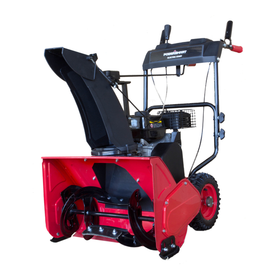
KNOWING YOUR SNOW THROWER Use the illustrations below to become familiar with the locations and functions of the various components and controls of this snow thrower. Fuel Tank Cap Tire Drive Control Handle Skid Shoe Chute Deflector Lever Discharge Chute Deflector Auger Control Handle Discharge Chute Chute Rotation Handle... - Page 11 Chute Direction Support Column Choke Lever Recoil Starter Handle Primer Bulb Fuel Valve Engine ON/OFF switch Drive Control Handle Located on the right side of the upper handle, the Drive Control Handle is used to engage and disengage the drive wheels. Squeeze the Drive Control Handle against the upper handle to engage the wheels; release to disengage.
-
Page 12: Assembly And Adjustments
ASSEMBLY AND ADJUSTMENTS The following section describes steps necessary to prepare the snow thrower for use. If after reading this section, you are unsure about how to perform any of the steps please call (800) 791-9458 Mon-Fri 9-5 EST for customer service. Failure to perform these steps properly can damage the snow thrower or shorten its life. - Page 13 3. Slide the crank handle through the mounting hole on upper handle. Mounting Hole 4. Attach the crank handle to the mount bracket onto the chute housing using spring locking pin. Spring Locking Pin Step 3 – Skid shoes installation and adjustments 1.
-
Page 14: Snow Thrower Preparation
SNOW THROWER PREPARATION ADD OIL The snow thrower is shipped without oil. User must add the proper amount of oil before operating the snow blower for the first time. The oil capacity of the engine crankcase is 20 fl. oz. For general use, we recommend 5W, 4-stroke engine oil. - Page 15 WARNING! Keep the area of operation free from foreign objects that can be thrown by the auger and/or impeller blades. Perform a thorough inspection of the area since some objects may be hidden from view by surrounding snow. If the Snow Thrower hits an obstruction or picks up a foreign object during use, stop the Snow Thrower, remove the obstruction, and inspect it for damage.
-
Page 16: Operating Your Snow Thrower
AUGER AND DRIVE CONTROLS 1. To engage the auger, press down on the auger control handle (left side handle). 2. To engage the drive, press down on the drive control handle (right side handle). The machine should start moving in the direction and speed that the speed control lever is set to. 3. -
Page 17: Maintenance
NOTICE: Do not change speed positions while the drive is engaged. Disengage the drive control handle BEFORE changing speeds or directions. If the snow is deeper than the height of the auger, remove it in several steps taking narrower swaths. Make several passes with the auger overlapping the cleared areas and reduce forward speed. -
Page 18: Storage & Cleaning
MAINTENANCE PROCEDURES TIRE INFLATION Before each use of your Snow Thrower, check the tire pressure. The pressure in each tire should be in the range of 20-24 psi for the best performance. The pressure can be checked using an ordinary tire pressure gauge. -
Page 19: Troubleshooting
TROUBLESHOOTING Problem Causes Remedy WARNING - Before attempting to make any inspections, repairs or adjustments, stop the engine, wait for all moving parts to stop moving and carefully disconnect the engine spark plug wire. If tipping or turning the snow blower is required for any inspection or repair, first wait until the engine is cool to the touch and then drain the engine of all fuel and oil into suitable containers and store or dispose of in a proper manner. -
Page 20: Exploded View And Parts List
EXPLODED VIEW AND PARTS LIST Auger Housing Assembly... - Page 21 Item Stock# Description 303020240 Hex flang bolts M8×20 303160192 Spacer 303071005 Idler Arm 303042013 flat washer 303030036 Locknut M8 303020492 Hex flang bolts M6×10 203010816 Belt Cover 303030077 flange surface Locknut M8 203100003 tensioning wheel Assembly 303020520 Spacer 303030032 Locknut M6 303071007 Guide Roller 303020146...
- Page 22 Auger assembly Item Stock# Description 303020244 Hex flang bolts M6×14 303042009 flat washer 303020248 Hex flang bolts M6×12 303071000 Keeper 303100045 bearing 6203RS 303070797 Bearing pressing plate seaming 303030077 Flange surface Locknut M8 303042013 flat washer 302080044 Snow scrape slice 303020161 Square Neck Bolt M8×25 303180903...
- Page 23 Frame assembly...
- Page 24 Item Stock# Description 303030087 flange surface Locknut 303100030 bearing 203021300 Bearing Housing 303170003 transmission shaft(2) 203050371 Big Frame Cover 303020444 Triangle outside hex flang bolt 303110016 Woodruff Key 303160656 Pulley Half 303043022 flat washer 303050066 Hex flang bolts 303020444 flange surface bolt M6X12 303030087 flange surface Locknut 303100030...
- Page 25 Chute Assembly...
- Page 26 Item Stock# Description 303010176 Hex Washer Screw 203050374 flat washer 303030087 flange surface Locknut 303020244 Hex flang bolts 203010819 Chute Fix-disk 303010176 Screw 203010820 Chute Rotary disk 203050376 Snow bucket 303010022 Screw 203050377 Chute 303130324 Torsional spring 302080047 Chute Cable 303160657 Chute Fix Link 303010176...
- Page 27 Handle Assembly Item Stock# Description Item Stock# Description Hex Washer Screw Self-tapping screw 303020240 303010237 M8x20 4x10 303080469 Lower handle 203070009 Rubber cover 303030026 Nut M8 303020274 Hex bolt M8x45 203020865 knob 203020380 Serrated washer Drive cable control 303043010 Saddle Washer 8 203021099 panel 303020139...
- Page 28 Engine Assembly...
- Page 29 Item Stock# Description 303020124 Hex Washer Screw 303210001 flat washer 303160195 small tension wheel sleeve 303160192 Spacer 303071023 Small Flat Idler(1) 303042005 flat washer 303020240 Hex flang bolts 303030077 flange surface Locknut 303030077 flange surface Locknut 303160193 Extension Spring 303160192 Spacer 303070202 Small Flat Idler...
- Page 30 ENGINE EXPLODED VIEW AND PARTS LIST...
-
Page 34: Two (2) Years Limited Warranty
Limited Warranty, you must return the entire power tool product; transportation prepaid, to PowerSmart Include a legible copy of the original receipt, which lists the date of purchase (month and year) and the name of the company purchased from.
Need help?
Do you have a question about the DB7004 and is the answer not in the manual?
Questions and answers