Advertisement
Owner's Guide and Installation Manual
Attach sales receipt to this card and retain as your proof of purchase
DATE OF PURCHASE:
MODEL NUMBER:
To register your fixture, please visit our website www.montecarlofans.com
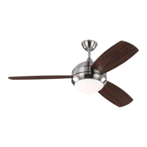
3DIR52XXD-V1 Series Fan
CUL Model NO. : 3DIR52XXD-V1
RETAILER NAME:
RETAILER ADDRESS:
8.2 kg
18 lbs
Total fan weight with light
Advertisement
Table of Contents

Related Manuals for Monte Carlo Fan Company 3DIR52 D-V1 Series


Summary of Contents for Monte Carlo Fan Company 3DIR52 D-V1 Series
- Page 1 Owner’s Guide and Installation Manual 3DIR52XXD-V1 Series Fan CUL Model NO. : 3DIR52XXD-V1 Attach sales receipt to this card and retain as your proof of purchase DATE OF PURCHASE: RETAILER NAME: RETAILER ADDRESS: MODEL NUMBER: To register your fixture, please visit our website www.montecarlofans.com 8.2 kg 18 lbs Total fan weight with light...
-
Page 2: Cautions And Warnings
Cautions and Warnings WARNING: TO REDUCE THE RISK OF FIRE, ELECTRIC SHOCK, OR INJURY TO PERSONS, OBSERVE THE FOLLOWING READ AND SAVE THESE INSTRUCTIONS Installation work and electrical wiring must be done by qualified person(s) in accordance with applicable codes and standards (ANSI/NFPA 70) including fire-rated construction. - Page 3 Mounting bracket Before you begin installing the fan, Switch Before installing this fan make sure the Use metal outlet box suitable for fan power off at Service panel and lock outlet box is properly installed to the support and use only the screws provided service disconnecting means to prevent house structure.
- Page 4 SAFETY CABLE INSTALLATION Black Wall switch (Live) White Blue White Black (Neutral) Ground/Green Lag screw Receiver Black Safety cable White Slot Washer Lock washer Install ball end of downrod into mounting For Canadian installation and for USA fan Make wiring connections using wire connectors provided as indicated above.
- Page 5 Plate on motor Light pan White LED light kit Blue Glass White Black Loosen 2 and remove 1 preassembled Loosen 2 and remove 1 preassembled Attach glass by locating dimples in light screw from the plate on motor. Save screw from light pan. Save screw for later pan with grooves on the glass and twist screw for later use.
- Page 6 REMOTE CONTROL SETTING (Dimming/Non Dimming) Dimming Non Dimming Setting The remote controller is set with dimming function at factory. The “DIM” selection is the light dimmable selection. If you would make the light with on/off feature, switch it to ON/OFF position. The “ON/OFF”...
-
Page 7: Remote Control Setting And Operation
REMOTE CONTROL SETTING and OPERATION Transmitter Operation 1. Remove the battery seat from the bottom of remote control Back side of transmitter and install battery. Replace the battery seat. (Fig. 3) transmitter Note: Use a 3V battery. The battery will weaken with age and should be replaced before leaking as this will damage the transmitter. - Page 8 REMOTE CONTROL SETTING and OPERATION The buttons on the remote control transmitter control the fan speed and light as follows. (Fig. 5) Press the button to get desired fan speed, Low to High and then High to Low cyclically. Press the OFF button to turn fan off. Fan speed will maintain last setting if turned off.
-
Page 9: Troubleshooting
Trouble Shooting or wiring. In some cases, these installation errors may be mistaken for defects. If you experience any faults, installation, please call our Customer Service Center at the number printed on your parts list insert sheet. Warning means to prevent power from being switched on accidentally. When the service disconnecting means cannot be locked, securely fasten a prominent warning device, such as a tag, to the service panel. - Page 10 Aug.2019 downrod mount only Jan.2020 battery seat and warning Feb.2020 branding...
Need help?
Do you have a question about the 3DIR52 D-V1 Series and is the answer not in the manual?
Questions and answers