Table of Contents
Advertisement
Quick Links
Advertisement
Table of Contents
Troubleshooting

Related Manuals for Welbilt Frymaster FPLHDC265


Summary of Contents for Welbilt Frymaster FPLHDC265
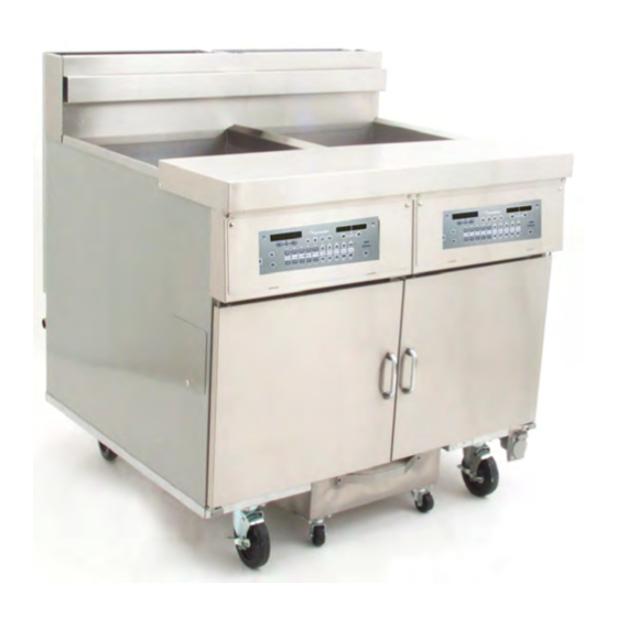
- Page 1 Your Growth Is Our Goal Decathlon High Efficiency FPLHDC265, FPLHDC365 Popeye’s CE Gas Fryer Service and Parts Manual This manual is updated as new information and models are released. Visit our website for the latest manual. *8197980* Part Number: FRY_SP_8197980 03/2022...
- Page 2 NOTICE IF, DURING THE WARRANTY PERIOD, THE CUSTOMER USES A PART FOR THIS FRYMASTER EQUIPMENT OTHER THAN AN UNMODIFIED NEW OR RECYCLED PART PURCHASED DIRECTLY FROM FRYMASTER, OR ANY OF ITS FACTORY AUTHORIZED SERVICERS, AND/OR THE PART BEING USED IS MODIFIED FROM ITS ORIGINAL CONFIGURATION, THIS WARRANTY WILL BE VOID.
-
Page 3: Table Of Contents
FPLHDC265, FPLHDC365 GAS FRYERS PARTS MANUAL TABLE OF CONTENTS CHAPTER 1: SERVICE PROCEDURES Functional Description ........................1-1 Accessing Fryers for Service ......................1-7 Cleaning the Gas Valve Vent Tube (if applicable) ................1-9 Adjusting Burner Manifold Gas Pressure ..................1-9 Adjusting the Pilot Flame ......................... -
Page 4: Chapter 1: Service Procedures
HIGH EFFICIENCY DECATHLON FPLHDC65 GAS FRYERS CHAPTER 1: SERVICE PROCEDURES 1.1 Functional Description Low Profile High Efficiency Decathlon (LHDC) Series gas fryers contain a welded stainless steel frypot heated by gas flames diffused evenly through tubes built into the frypot. Flames originate from orifices in a burner manifold positioned beneath cast-steel burners. - Page 5 HIGH EFFICIENCY DECATHLON FPLHDC65 GAS FRYERS CHAPTER 1: SERVICE PROCEDURES Pilot System Configuration The pilot system is comprised of the pilot orifice, pilot hood, and a thermopile (some systems incorporate a thermocouple). The pilot serves two purposes: light the burner and heat the thermopile.
- Page 6 HIGH EFFICIENCY DECATHLON FPLHDC65 GAS FRYERS CHAPTER 1: SERVICE PROCEDURES Electronic Ignition Configuration (cont.) At start-up the ON/OFF switch is placed in the ON position, supplying 12 VDC to the heat control circuitry in the controller or controller and to one side of the heat relay coil on the interface board.
- Page 7 HIGH EFFICIENCY DECATHLON FPLHDC65 GAS FRYERS CHAPTER 1: SERVICE PROCEDURES commands from one central point. Two types of interface boards may be used in LHDC Series gas fryers; the type used depends on the fryer configuration. In units configured for electronic ignition and constant pilot, P/N 826-2434 is used; in units configured with a manually lit pilot (non-electronic ignition), P/N 826-2425 is used.
- Page 8 HIGH EFFICIENCY DECATHLON FPLHDC65 GAS FRYERS CHAPTER 1: SERVICE PROCEDURES Interface Boards (cont.) 826-2434: These interface boards are used in LHDC fryers equipped with electronic ignition and constant pilot. INTERFACE BOARD P/N 826-2434 Used on fryers equipped with electronic ignition and constant pilot.
- Page 9 HIGH EFFICIENCY DECATHLON FPLHDC65 GAS FRYERS CHAPTER 1: SERVICE PROCEDURES Interface Boards (cont.) FREQUENTLY USED TEST POINTS FOR HIGH EFFICIENCY DECATHLON (LHDC) FRYERS 106-6669 INTERFACE BOARD Test Meter Setting Pins Test Results 12VAC Power to Controller 50 VAC Scale 1 and 3 on J3 12-18 12VDC Power to Right BL Relay 50 VDC Scale...
-
Page 10: Accessing Fryers For Service
HIGH EFFICIENCY DECATHLON FPLHDC65 GAS FRYERS CHAPTER 1: SERVICE PROCEDURES Thermostats Different types of thermostats are used in High Efficiency Decathlon Series gas fryers, depending on fryer configuration. Fryers equipped with a Thermatron use a dial to adjust temperature. In this configuration, the probe resistance varies inversely with the temperature. - Page 11 HIGH EFFICIENCY DECATHLON FPLHDC65 GAS FRYERS CHAPTER 1: SERVICE PROCEDURES Restraints Once the fryer has been positioned at the frying station, use a carpenter’s level placed across the top of the frypot to verify that the unit is level, both side-to-side and front-to-back. To level fryers equipped with legs, the bottom of the legs can be screwed out up to one inch for leveling.
-
Page 12: Cleaning The Gas Valve Vent Tube (If Applicable)
HIGH EFFICIENCY DECATHLON FPLHDC65 GAS FRYERS CHAPTER 1: SERVICE PROCEDURES 1.3 Cleaning the Gas Valve Vent Tube (if applicable) 1. Set the fryer power switch and the gas valve to the OFF position. 2. Carefully unscrew the vent tube from the gas valve. NOTE: The vent tube may be straightened for ease in removal. -
Page 13: Adjusting The Pilot Flame
HIGH EFFICIENCY DECATHLON FPLHDC65 GAS FRYERS CHAPTER 1: SERVICE PROCEDURES 1.5 Adjusting the Pilot Flame 1.5.1 Main Pilot 1. Remove the cap from the pilot adjustment screw hole on the gas valve. 2. Using a small, flat-tipped screwdriver, turn the pilot adjusting screw counterclockwise to increase length of flame or clockwise to decrease length of flame. -
Page 14: Replacing Fryer Components
HIGH EFFICIENCY DECATHLON FPLHDC65 GAS FRYERS CHAPTER 1: SERVICE PROCEDURES 1.7 Replacing Fryer Components 1.7.1 Replacing the Controller 1. Disconnect the fryer from the electrical supply. 2. Unscrew the two controller panel screws. The controller panel is hinged at the bottom and will swing open from the top. - Page 15 HIGH EFFICIENCY DECATHLON FPLHDC65 GAS FRYERS CHAPTER 1: SERVICE PROCEDURES 1.7.2 Replacing Control Box Components including Ignition Module, Interface Board, Transformers, etc. Disconnect the fryer from the electrical supply. Unscrew the two controller panel screws. The controller panel is hinged at the bottom and will swing open from the top.
- Page 16 HIGH EFFICIENCY DECATHLON FPLHDC65 GAS FRYERS CHAPTER 1: SERVICE PROCEDURES 1.7.3 Replacing the Temperature Probe; Controller-equipped Fryers 1. Disconnect the fryer from the electrical supply. 2. Drain cooking oil from the frypot. Allow the frypot cool completely before proceeding. 3. Remove fryer door for easier access to the temperature probe.
- Page 17 HIGH EFFICIENCY DECATHLON FPLHDC65 GAS FRYERS CHAPTER 1: SERVICE PROCEDURES drain valves, and working them gently out of the rubber boots. Set aside for reassembly. 1.7.3 Replacing the Temperature Probe; Controller-equipped Fryers (cont.) 6. Remove the burner shield by loosening the screw on each end.
- Page 18 HIGH EFFICIENCY DECATHLON FPLHDC65 GAS FRYERS CHAPTER 1: SERVICE PROCEDURES 1.7.3 Replacing the Temperature Probe; Controller-equipped Fryers (cont.) 10. Locate the temperature probe inside the frypot. Locate the temperature probe. 11. The temperature probe can be removed through the bottom of the frypot as follows: Ensure the two-pin connector has been removed from the probe wiring harness (step 4, above).
- Page 19 HIGH EFFICIENCY DECATHLON FPLHDC65 GAS FRYERS CHAPTER 1: SERVICE PROCEDURES Installing the New Temperature Probe: 1. Feed the probe wire through the probe nipple from the top side of the frypot. 2. Loosely install the bladder nut. 3. Mount the probe into the mounting hardware. Carefully bend the two tabs back into alignment to retain probe.
- Page 20 HIGH EFFICIENCY DECATHLON FPLHDC65 GAS FRYERS CHAPTER 1: SERVICE PROCEDURES 1.7.4 Replacing the High-limit Thermostat (cont.) 6. Locate the high-limit probe inside the frypot. Carefully bend the outer tab at the rear of the Compression nut unscrewed. Unscrew high limit until the high limit can slid back and the pass-through nut (arrow).
- Page 21 HIGH EFFICIENCY DECATHLON FPLHDC65 GAS FRYERS CHAPTER 1: SERVICE PROCEDURES 7. Carefully pull high-limit capillary tube and bulb out of the frypot from the bottom. Remove high-limit capillary tube and bulb from the bottom of the frypot. 1.7.4 Replacing the High-limit Thermostat (cont.) 8.
- Page 22 HIGH EFFICIENCY DECATHLON FPLHDC65 GAS FRYERS CHAPTER 1: SERVICE PROCEDURES 9. Remove high-limit from fryer by pulling the capillary tube and bulb through the component box opening (arrow). This may require removal of the control panel frame. 10. Reverse the above steps for high-limit installation. IMPORTANT: When installing new high-limit, ensure the capillary tube and bulb are positioned properly Component box opening (arrow).
- Page 23 HIGH EFFICIENCY DECATHLON FPLHDC65 GAS FRYERS CHAPTER 1: SERVICE PROCEDURES 1.7.5 Replacing Rocker Switches (cont.) 3. Depress the retaining clips (see illustration below) and push the switch out of the slot. If there is a switch-guard present, retain it for installation of the replacement switch. Depress clips on each side to remove switch from control panel.
- Page 24 HIGH EFFICIENCY DECATHLON FPLHDC65 GAS FRYERS CHAPTER 1: SERVICE PROCEDURES 7. Reverse steps 1-5 to install the replacement gas valve. 1.7.7 Replacing the Pilot Assembly 1. Remove the pilot tubing from the bottom of the pilot assembly. 2. If the pilot is an electronic ignition pilot, disconnect the ignition cable and the sense wire. 3.
- Page 25 HIGH EFFICIENCY DECATHLON FPLHDC65 GAS FRYERS CHAPTER 1: SERVICE PROCEDURES 1.7.9 Replacing the Frypot 1. Open fryer doors and remove filter pan (if applicable). Ensure controller and all power switches are off. Drain and dispose of or store oil from all frypots prior to moving fryer. DANGER Hot cooking oil will cause severe burns.
- Page 26 HIGH EFFICIENCY DECATHLON FPLHDC65 GAS FRYERS CHAPTER 1: SERVICE PROCEDURES 8. Remove back panels of the fryer. There may be both upper and lower panels and several screws secure them. Screw location and orientation will vary according to fryer model. Typical screw locations on the back panel (may vary by model).
- Page 27 HIGH EFFICIENCY DECATHLON FPLHDC65 GAS FRYERS CHAPTER 1: SERVICE PROCEDURES 10. Remove screws securing flue cap to frypot (access from above; a nut-driver with an extension or long screwdriver is required). Use care not to drop the screws into the flues. If this happens, the screws can be retrieved when the flue is removed (Step 12).
- Page 28 HIGH EFFICIENCY DECATHLON FPLHDC65 GAS FRYERS CHAPTER 1: SERVICE PROCEDURES 13. Remove the clevis clip and oil return handle rod from the oil return valve at the rear of the fryer. Slip Section A of the clevis clip off of the oil return handle by pulling up on the rings.
- Page 29 HIGH EFFICIENCY DECATHLON FPLHDC65 GAS FRYERS CHAPTER 1: SERVICE PROCEDURES 15. Remove the drain manifold. Only the drain tubes directly blocking the frypot being replaced require removal. Remove the nuts holding the drain valve strap onto the drain tube stud. Disconnect the Teflon tube at the back of the center dump tube piece and any other components attached to the tubes,...
- Page 30 HIGH EFFICIENCY DECATHLON FPLHDC65 GAS FRYERS CHAPTER 1: SERVICE PROCEDURES 19. Remove the burner rail when all burners have been uninstalled. Loosen the screws on each end of the rail and set it aside. 20. If the fryer is equipped with drain-valve microswitches, mark the wires and microswitch terminals, then disconnect wires from the switch.
- Page 31 HIGH EFFICIENCY DECATHLON FPLHDC65 GAS FRYERS CHAPTER 1: SERVICE PROCEDURES 22. Remove the pilot assembly from the frypot. - If trailing pilot, disconnect the pilot supply line from the trailing pilot valve on the burner manifold. Remove the mounting screw(s) to detach the pilot assembly from the pilot bracket.
- Page 32 HIGH EFFICIENCY DECATHLON FPLHDC65 GAS FRYERS CHAPTER 1: SERVICE PROCEDURES 28. Remove frypot from fryer by lifting up and out. Lifting frypot from fryer. 29. Position the frypot upside down on a suitable work surface 30. Record position of the valve stem in relation to the frypot prior to removing the drain valve.
-
Page 33: Troubleshooting And Problem Isolation
HIGH EFFICIENCY DECATHLON FPLHDC65 GAS FRYERS CHAPTER 1: SERVICE PROCEDURES 1.8 Troubleshooting and Problem Isolation Because it is not feasible to include every issue that might occur, this section is intended to provide technicians with a general knowledge of the broad problem categories associated with this equipment and the probable causes of each. - Page 34 HIGH EFFICIENCY DECATHLON FPLHDC65 GAS FRYERS CHAPTER 1: SERVICE PROCEDURES 1.8.1 Ignition Failure (cont.) The Electronic Circuits If gas and electrical power are supplied to the fryer, the next most likely cause of ignition failure is a problem in the 24 VAC circuit of fryers equipped with electronic ignition systems, or in the pilot system for those without electronic ignition.
- Page 35 HIGH EFFICIENCY DECATHLON FPLHDC65 GAS FRYERS CHAPTER 1: SERVICE PROCEDURES 1.8.2 Improper Burner Function (cont.) If popping occurs only during peak operating hours, the problem may be incorrect or fluctuating gas pressure. Verify that the incoming gas pressure (pressure to the gas valve) is in accordance with the appropriate requirements listed in the Installation and Operation manual that came with the fryer, and that the pressure remains constant throughout all hours of usage.
- Page 36 HIGH EFFICIENCY DECATHLON FPLHDC65 GAS FRYERS CHAPTER 1: SERVICE PROCEDURES 1.8.2 Improper Burner Function (cont.) Burners lighting on the left side only may be caused by a trailing pilot problem (four- and five- tube frypots) or improper burner manifold pressure. Fluctuating flame intensity is normally caused by either improper or fluctuating incoming gas pressure but may also be the result of variations in the kitchen atmosphere.
- Page 37 HIGH EFFICIENCY DECATHLON FPLHDC65 GAS FRYERS CHAPTER 1: SERVICE PROCEDURES 1.8.4 Improper Controller Function Sensitivity or "Stretch Time." Sensitivity—or stretch time—is a programmable feature that increases the cook time countdown based on variations in the oil temperature from the setpoint (e.g., when cold product is dropped into the oil, causing the oil temperature to drop). The sensitivity for each product button has 10 settings (0 through 9).
- Page 38 HIGH EFFICIENCY DECATHLON FPLHDC65 GAS FRYERS CHAPTER 1: SERVICE PROCEDURES 1.8.5 Improper Filtration Function The majority of filtration problems arise from operator error. One of the most common errors is placing the filter paper on the bottom of the filter pan rather than over the filter screen. Anytime the pump is running, but no oil is being filtered, check the installation and size of the filter paper.
- Page 39 HIGH EFFICIENCY DECATHLON FPLHDC65 GAS FRYERS CHAPTER 1: SERVICE PROCEDURES 1.8.5 Improper Filtration Function (cont.) Incorrectly sized or installed paper will allow food particles and sediment to pass through and clog the suction tube on the bottom of the filter carriage. Particles large enough to block the suction tube may indicate that the crumb tray is not being used.
- Page 40 HIGH EFFICIENCY DECATHLON FPLHDC65 GAS FRYERS CHAPTER 1: SERVICE PROCEDURES 1.8.6 Frypot Leakage Frypot leaks are almost always due to improperly sealed high-limit, thermostats/temperature probe and drain fittings. When installed or replaced, each of these components must be sealed with Loctite PST567 sealant or equivalent to prevent leakage. In very rare cases, a leak may develop along one of the welded edges of the frypot, or where the tube is welded to the frypot.
- Page 41 HIGH EFFICIENCY DECATHLON FPLHDC65 GAS FRYERS CHAPTER 1: SERVICE PROCEDURES 1.8.7 Improper Basket Lift Function Bell-Crank Basket Lifts Most High Efficiency Decathlon Series gas fryers are equipped with a bell-crank style basket lift. A cam and a bell crank are connected to the basket lift arm by a flat metal link.
-
Page 42: Troubleshooting Guides
HIGH EFFICIENCY DECATHLON FPLHDC65 GAS FRYERS CHAPTER 1: SERVICE PROCEDURES Troubleshooting Guides The following troubleshooting guides are intended to assist service technicians in quickly isolating the probable causes of equipment malfunctions by following a logical, step-by-step process. PROBLEM PROBABLE CAUSES CORRECTIVE ACTION Burner will not ignite. - Page 43 HIGH EFFICIENCY DECATHLON FPLHDC65 GAS FRYERS CHAPTER 1: SERVICE PROCEDURES PROBLEM PROBABLE CAUSES CORRECTIVE ACTION B. Air in gas supply lines (new B. Allow unit to cycle on and off for installation). approximately 30 minutes to force air from gas manifold and lines. Electronic/operating A.
-
Page 44: Wiring Diagrams
HIGH EFFICIENCY DECATHLON FPLHDC65 GAS FRYERS CHAPTER 1: SERVICE PROCEDURES 1.10 Wiring Diagrams Note: The diagrams in this section depict wiring as of the date of manual publication. It may not reflect design changes made to the equipment after publication. Refer to the wiring diagram affixed to the unit when actually troubleshooting this equipment. - Page 45 HIGH EFFICIENCY DECATHLON FPLHDC65 GAS FRYERS CHAPTER 1: SERVICE PROCEDURES 1.10.2 3000 Controller 1-42...
-
Page 46: Probe Resistance Chart
HIGH EFFICIENCY DECATHLON FPLHDC65 GAS FRYERS CHAPTER 1: SERVICE PROCEDURES 1.11 Probe Resistance Charts Controller Probe Resistance Chart ° Celsius ° Fahrenheit Ohms (±3%) 1080 1101 1122 1143 1164 1185 1206 1226 1247 1268 1289 1309 1330 1350 1371 1391 1412 1432 1453... -
Page 47: Chapter 2: Parts List
HIGH EFFICIENCY DECATHLON FPLHDC65 GAS FRYERS CHAPTER 2: PARTS LIST 2.1 High Efficiency Decathlon (FPLHDC65) Primary Components... - Page 48 HIGH EFFICIENCY DECATHLON FPLHDC65 GAS FRYERS CHAPTER 2: PARTS LIST 2.1.1 High Efficiency Decathlon (FPLHDC65) Primary Components (cont.) ITEM PART # DESCRIPTION 823-7565 Frypot - S/S Filter 823-7567 Frypot – S/S Non-Filter ►►► See Orifices, Section 2.2 See Additional Components and Controllers, Section 2.3 ⁄...
-
Page 49: Orifices
HIGH EFFICIENCY DECATHLON FPLHDC65 GAS FRYERS CHAPTER 2: PARTS LIST 2.2 Orifices ITEM PART # COMPONENT Natural Orifices 810-2060 2.40 mm CE 810-3801 2.35 mm (China) 810-3132 2.20 mm 810-2938 0-1999 ft. 2.26mm 810-3053 2000-3999 ft. 2.18mm 810-3054 4000-5999 ft. 2.10mm 810-2058 2.08mm #45 810-4285... -
Page 50: Additional Optional Components And Controllers
HIGH EFFICIENCY DECATHLON FPLHDC65 GAS FRYERS CHAPTER 2: PARTS LIST 2.3 Additional Components and Controllers ITEM PART # DESCRIPTION 807-3680 High-limit Thermostat, Manual Reset 450° F (232° C) 210-4628 Bracket, Frypot Sensors (requires tack welding to heat tube) 210-4629 Bracket, Frypot Controller Probe (requires tack welding to heat tube) 807-1321 Fuse Holder, Buss 807-3843... - Page 51 HIGH EFFICIENCY DECATHLON FPLHDC65 GAS FRYERS CHAPTER 2: PARTS LIST 2.3 Additional Components and Controllers (cont.) ITEM PART # DESCRIPTION 826-2434 Interface Board Standing Pilot 826-2425 Interface Board Basket Lift 807-4199 Cable Assembly, SMT Controller to Interface Board 807-4597 Control Harness D-Series Wiring 108-2987 Harness Assy, W/ Computer D60 CE FS Gas Valves...
-
Page 52: Drain Components
HIGH EFFICIENCY DECATHLON FPLHDC65 GAS FRYERS CHAPTER 2: PARTS LIST 2.4 Drain System Components 2.4.1 3" Drain Manifold Components To drain valve. To drain valve. - Page 53 HIGH EFFICIENCY DECATHLON FPLHDC65 GAS FRYERS CHAPTER 2: PARTS LIST 2.4.1 3" Drain Manifold Components (cont.) ITEM PART # DESCRIPTION 823-5188 Tube, 3" Filter Right, 50/60/80 823-7664 Tube, 3” Drain Middle BK50 of BK60/50/60 823-8167 Tube, 3” Drain YSCFHC318 823-4681 Tube, 3"...
- Page 54 HIGH EFFICIENCY DECATHLON FPLHDC65 GAS FRYERS CHAPTER 2: PARTS LIST 2.4.2 Drain Valve Assembly ITEM PART # DESCRIPTION 108-3474SP Valve Assy, 1 ½” Drain 810-2783 Valve, 1 ½” Full Port Drain 200-1257 Retainer, Drain Valve Nut 200-6116 Strap, Round Drain Connecting 901-2348 Cover, DV Safety Switch 807-4956...
-
Page 55: Oil Return System
HIGH EFFICIENCY DECATHLON FPLHDC65 GAS FRYERS CHAPTER 2: PARTS LIST 2.5 Oil Return System... - Page 56 HIGH EFFICIENCY DECATHLON FPLHDC65 GAS FRYERS CHAPTER 2: PARTS LIST 2.5 Oil Return System (cont.) ITEM PART # DESCRIPTION 106-4006SP Valve Assembly, ½" Oil Return (see Section 2.6 for components) 106-7598SP Valve, Solenoid with Female Pins 200-9295 Handle, Oil Return (HD 65) 200-8929 Handle, Oil Return (YSCFC 18) 809-0601...
-
Page 57: Additional Oil Return Components
HIGH EFFICIENCY DECATHLON FPLHDC65 GAS FRYERS CHAPTER 2: PARTS LIST 2.6 Additional Oil Return Components 2-11... - Page 58 HIGH EFFICIENCY DECATHLON FPLHDC65 GAS FRYERS CHAPTER 2: PARTS LIST 2.6 Additional Oil Return Components (cont.) ITEM PART # DESCRIPTION Oil Return Manifold 810-3118 2-Battery 810-3121 3-Battery 810-3120 4- Battery Pump 810-4377 8 GPM, Viking (CCW Only) 807-11973 Viking Pump Seal Kit 816-0093 Gasket (Pump/Motor) (included with motor) Motor and Gasket Kit...
-
Page 59: Plumbing Front Oil Dispose/Wash Down Filtration
HIGH EFFICIENCY DECATHLON FPLHDC65 GAS FRYERS CHAPTER 2: PARTS LIST 2.7 Plumbing Front Oil Dispose/Wash Down Filtration TO OIL RETURN MANIFOLD ITEM PART # COMPONENT 1085922 STUD ASSY, WASTE VALVE 1088882 PLATE ASS'Y, MOUNTNG DISPOSE 2401917 HANDLE, VALVE FRONT DISPOSE 8072103 SWITCH, CE MICROSWITCH STRAIGHT LEVER 8160220... - Page 60 HIGH EFFICIENCY DECATHLON FPLHDC65 GAS FRYERS CHAPTER 2: PARTS LIST 2.7 Plumbing Front Oil Dispose/Wash Down Filtration cont. ITEM PART # COMPONENT 8100490 QUICK DISCONNECT ½” FEMALE ADAPTER, FEMALE ⅝” OD X ½” 8101669 1080528SP HOSE ASSY, WASH DOWN 1061454 NOZZLE ASSY, W/HANDLE 8100487 QUICK DISCONNECT, ½”...
-
Page 61: Over-The-Top Oil Return System
HIGH EFFICIENCY DECATHLON FPLHDC65 GAS FRYERS CHAPTER 2: PARTS LIST 2.8 Over-the-Top Oil Return System ITEM PART # DESCRIPTION Adapter, Female ⅞" O.D. x ½" 810-1669 Flexline, ⅝" I.D. x 6.50" Long 810-1680 810-2513 Tubing, Faucet Upper 810-2699 Coupling, Quick Disconnect, Snaptite 810-2700 Nipple, Quick Disconnect, Snaptite 810-3234... -
Page 62: Filtration Components
HIGH EFFICIENCY DECATHLON FPLHDC65 GAS FRYERS CHAPTER 2: PARTS LIST 2.9 Filtration Components 2.9.1 Filtration Components; 65 Series Fryers (Filter Leaf Option) ITEM PART # DESCRIPTION 823-5851 Basket, Crumb 106-6466SP Filter Leaf with Suction Tube Assembly 106-8399 Filter Leaf (screen only) 823-5258SP Filter Pan 810-2805... - Page 63 HIGH EFFICIENCY DECATHLON FPLHDC65 GAS FRYERS CHAPTER 2: PARTS LIST 2.9.2 Filtration Components; 65 Series Fryers (Popeye’s Filter Paper Option) ITEM PART # DESCRIPTION 823-7769SP Filter Pan SCFHD65 810-2805 Caster, 2" 812-2301 Screen, Sana Grid UFF60 810-3540 Ring, Hold-down UFF60 823-8659 Basket, Crumb 65 813-0568...
-
Page 64: Accessories
HIGH EFFICIENCY DECATHLON FPLHDC65 GAS FRYERS CHAPTER 2: PARTS LIST 2.10 Accessories 2-18... -
Page 65: Flexlines
HIGH EFFICIENCY DECATHLON FPLHDC65 GAS FRYERS CHAPTER 2: PARTS LIST 2.10 Accessories (cont.) ITEM PART # DESCRIPTION 106-2897SP Cover (FPHD65) 810-0180 Handle, Vat Cover 823-3938 Crumb Scoop 803-0278 L-shaped Brush 810-3066 Grid assembly, rack 803-0197 Fryer’s Friend 803-0427 Basket, Twin 803-0099 Basket, Full 8030289... - Page 66 FRYMASTER 8700 LINE AVENUE, SHREVEPORT, LA 71106-6800 800-551-8633 318-865-1711 WWW.FRYMASTER.COM EMAIL: FRYSERVICE@WELBILT.COM ©2022 Welbilt Inc. except where explicitly stated otherwise. All rights reserved. Continuing product improvement may necessitate change of specifications without notice. Part Number FRY_SP_8197980 03/2022...
Need help?
Do you have a question about the Frymaster FPLHDC265 and is the answer not in the manual?
Questions and answers