Advertisement
Quick Links
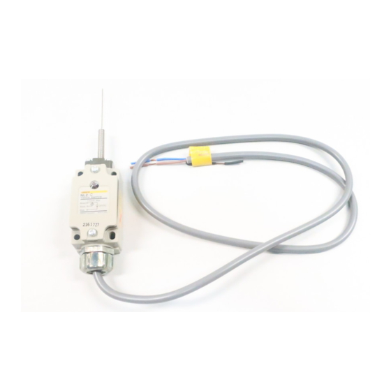
Limit Touch Switch
NL
Object Actuates Switch and Turns
Built-in Monitor Indicator ON
• Instantaneous operation upon contact with extremely
limited hysteresis for high-precision position detection.
• Detects minute displacement or lightweight objects with
minimal operating force.
• Built-in LED indicator ensures easy operation monitoring.
• DC models provide versatile functions in combination
with the S3D2 Sensor Controller.
Be sure to read Safety Precautions on page 6 to 7 and
Safety Precautions for All Limit Switches.
Application Examples
· Detection of press completion position.
· Detection of mistakes in workpiece
setting or removal.
· Detection of minute workpieces.
Press
Workpiece
NL
· Displacement detection and control.
Pressure
Bellows
Controller
Unit
NL
· Drill positioning.
· Material positioning.
NL
NL
· Thickness control of rolling plates.
NL
Controller
Unit
· Detection of workpiece edges.
NL
Grounding
rod
· Detection of paper or cloth edge
(using indirect grounding).
Roller
· Detection of paper or cloth seam
(using indirect grounding).
NL
Motor
Paper (cloth)
CSM_NL_DS_E_2_1
NL
Paper (cloth)
Grounding
rod
(Ground)
NL
Paper (cloth)
Ground side
NL
Grounding rod
1
Advertisement

Related Manuals for Omron NL1-C


Summary of Contents for Omron NL1-C
- Page 1 Limit Touch Switch CSM_NL_DS_E_2_1 Object Actuates Switch and Turns Built-in Monitor Indicator ON • Instantaneous operation upon contact with extremely limited hysteresis for high-precision position detection. • Detects minute displacement or lightweight objects with minimal operating force. • Built-in LED indicator ensures easy operation monitoring. •...
-
Page 2: Ordering Information
NL3-P 100V 200 VAC NL3-C 200V NL3-P 200V Antenna only NL1-C ANTENNA ASSY (Same for NL1, NL2, and NL3) Note: Each model is provided with a standard 1-m cable. Separate Antenna Model Model Separate antenna model Features · Antenna with 3-m extension cable is available for narrow spaces where conventional limit switches cannot be used. -
Page 3: Principle Of Operation
Applicable model Sensor Controller Function Power supply voltage S3D2-AK Basic operation S3D2-BK Memory and timer operation 100 to 240 VAC S3D2-CK Timer operation S3D2-AKD Basic operation 24 VDC S3D2-CKD Timer operation Contact your OMRON representative for the datasheet of the S3D2. -
Page 4: External Connection
Be sure to wire the cable correctly according to the color of each lead wire. Do not wire power lines or high-tension lines alongside the cable. The use of S3D2 is recommended as a power supply to the NL1. Contact your OMRON representative for the datasheet of the S3D2. +12 VDC Brown (Red) - Page 5 Note: 1. The force that pushes the actuator must not exceed 1.96 N. Note: Do not apply a force greater than 9.8 N to the plunger. 2. The antenna is replaceable. Contact your OMRON representative for details. Separated Antenna Models The dimensions provided for the NL1-SP, NL2-SP, NL1-SC, and NL2-SC are the external dimensions for the antennas.
-
Page 6: Safety Precautions
Safety Precautions Refer to Safety Precautions for All Limit Switches. Antenna CAUTION <Shape and Extension> Make sure that the antenna does not come into contact If a metal plate is used as an antenna by connecting it to the built-in with the human body, otherwise an electric shock may or separated antenna of the NL, the surface area of the metal plate be received. - Page 7 NBR may deteriorate. Contact 4 cm min. your OMRON representative for details. • Make sure that the load is connected according to the connection diagram. The internal circuit of the NL will break due to mistakes in wiring or load short-circuiting.