Advertisement
Quick Links
INSTRUCTION MANUAL
ANALOG BACKUP STATION
BEFORE USE ....
Thank you for choosing M-System. Before use, please check
contents of the package you received as outlined below.
If you have any problems or questions with the product,
please contact M-System's Sales Office or representatives.
■ PACKAGE INCLUDES:
Analog backup station (body + base socket) ......................(1)
■ MODEL NO.
Confirm Model No. marking on the product to be exactly
what you ordered.
■ INSTRUCTION MANUAL
This manual describes necessary points of caution when
you use this product, including installation, connection,
hardware setting and basic maintenance procedures.
When you need to change software settings, please refer to
the Operation Manual for Model PU-2x (EM-9255), Section
A.
POINTS OF CAUTION
■ POWER INPUT RATING & OPERATIONAL RANGE
• Locate the power input rating marked on the product and
confirm its operational range as indicated below:
11 – 35V DC rating: Approx. 120mA at 24V in CAS mode
Approx. 180mA at 24V in MAN mode
■ GENERAL PRECAUTIONS
• Before you remove the unit from its base socket or mount
it, turn off the power supply and input signal for safety.
■ ENVIRONMENT
• Indoor use.
• When heavy dust or metal particles are present in the
air, install the unit inside proper housing with sufficient
ventilation.
• Do not install the unit where it is subjected to continuous
vibration. Do not subject the unit to physical impact.
• Environmental temperature must be within -5 to +55°C
(23 to 131°F) with relative humidity within 30 to 90% RH
in order to ensure adequate life span and operation.
■ WIRING
• Do not install cables close to noise sources (relay drive
cable, high frequency line, etc.).
• Do not bind these cables together with those in which
noises are present. Do not install them in the same duct.
■ AND ....
• The unit is designed to function as soon as power is
supplied, however, a warm up for 10 minutes is required
for satisfying complete performance described in the data
sheet.
5-2-55, Minamitsumori, Nishinari-ku, Osaka 557-0063 JAPAN
Phone: +81(6)6659-8201 Fax: +81(6)6659-8510 E-mail: info@m-system.co.jp
MODEL
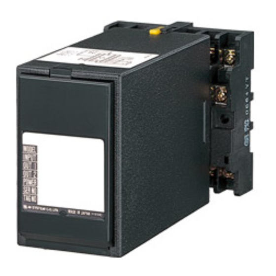
COMPONENT IDENTIFICATION
Body
Connection Diagram
Front Cover
Specifications
■ HOW TO OPEN THE FRONT COVER:
Hang your finger on the hook at the top of the front cover
and pull.
The shape of base socket may be different
for some models.
INSTALLATION
Detach the yellow clamps located at the top and bottom of
the unit for separate the body from the base socket.
■ DIN RAIL MOUNTING
Set the base socket so that its
DIN rail adaptor is at the bot-
tom. Hang the upper hook at
the rear side of base socket on
the DIN rail and push in the
lower.
When removing the
socket, push down the DIN
rail adaptor utilizing a minus
screwdriver and pull.
■ WALL MOUNTING
Refer to "EXTERNAL DI-
MENSIONS."
JB2
Base Socket
Clamp
(top & bottom)
DIN Rail
35mm wide
Spring Loaded
DIN Rail Adaptor
Shape and size of the base socket
are slightly different with various
socket types.
EM-2642 Rev.3 P. 1 / 5
Advertisement

Related Manuals for M-system JB2


Summary of Contents for M-system JB2
- Page 1 ANALOG BACKUP STATION MODEL BEFORE USE ..COMPONENT IDENTIFICATION Thank you for choosing M-System. Before use, please check Body Base Socket contents of the package you received as outlined below. If you have any problems or questions with the product, Connection Diagram please contact M-System’s Sales Office or representatives.
- Page 2 4 – 20mA DC RE-TRANSMITTED OUTPUT – MAN COMMAND 4 – 20mA DC MAN STATUS CONTACT DOWN RUN CONTACT POWER – MODULAR JACK PU-2x EM-2642 Rev.3 P. 2 / 5 5-2-55, Minamitsumori, Nishinari-ku, Osaka 557-0063 JAPAN Phone: +81(6)6659-8201 Fax: +81(6)6659-8510 E-mail: info@m-system.co.jp...
- Page 3 Output in % after power on in manual control mode Selectable range: -25.00 to 125.00 (factory set value: -25.00) Output value after power on (see “JB2 Actions when the Power Supply is Recovered after Failure.”) 0: HOLD VALUE The value stored at the moment of power failure...
- Page 4 ■ TRANSITION FROM MAN TO CAS CONTROL MODE The JB2 increases/decreases the MV output until it reaches to the same value as the CAS control signal, and turns on to CAS control mode. The response time constant can be set/changed with the PU-2x.
- Page 5 For JB2/A, the operation at power recovery is selectable (ITEM 30, 31). When JB2 (without “/A”) is replaced with JB2/A compatibly, set JB2/A according to the ITEM 21 value of JB2 as following. • When JB2 is set ITEM 21 as 1 (DIRECT) or as 2 (TRACE BACK) Set JB2/A ITEM 30 as -25% and ITEM 31 as 0 (HOLD VALUE) •...
Need help?
Do you have a question about the JB2 and is the answer not in the manual?
Questions and answers