FUTABA T32MZ Setting Manual
Hide thumbs
Also See for T32MZ:
- Instruction manual (189 pages) ,
- Manual (31 pages) ,
- Setting manual (10 pages)
Advertisement
Quick Links
Advertisement

Related Manuals for FUTABA T32MZ


Summary of Contents for FUTABA T32MZ
- Page 1 T32MZ GYA553 Ver.2 Setting manual 1M23Z06823...
- Page 2 By installing the latest software (Ver. 3.6 ~) on the T32MZ, you can setting the airplane gyro GYA553 on the T32MZ. Connection T32MZ and GYA553 T32MZ S.I/F Reciver Connection Cable (included with gyro) GYA553 CAUTION Be sure to connect and disconnect the GYA553 and T32MZ connection cable with the power off.
- Page 3 SETTING 1. Select “Gyro setting” on the last page of Airplane Model Menu * At this time, if Gyro is not connected to T32MZ by wire, this screen appears. When "GY Settings Transfer" is selected, the gyro setting data saved in T32MZ is written to the gyro. 2. Select "Start" Tap "Yes" to display the GYA553 data saved in T32MZ. Select "Start" This will download the gyro data to the T32MZ. To Basic menu 3. Home screen is displayed ◆ When copying data from Gyro A to Gyro B Connect the gyro A to the T32MZ and press [Start]. (Enter the data of A into T32MZ) If you press Start here, the B data will be download to the T32MZ and the A data will be lost. Connect Gyro B to T32MZ and press [GY Settings Transfer]. (Put data on A into gyro B)
- Page 4 Home screen Home screen On the home screen, basic information such as gyro operation mode, sensitivity, battery voltage are displayed. Gyro operation mode / Gyro Battery voltage gain Displays the voltage of the Displays "AVCS" or "Normal" receiver battery connected to opera-tion mode and gyro GYA.
- Page 5 Config Config Config 1/7 Gyro set mounting direction Set the mounting direction of GYA. Set mounting direction Config 1/7 WING/TAIL Set with the wing type/tail type of GYA553. The wing type/tail type of the transmitter is not used and is normal. ・ ・ ・ Select wing type Select tail type...
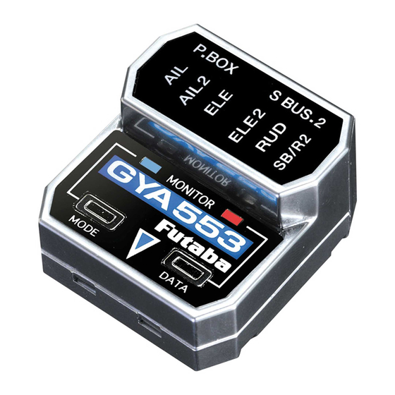
- Page 6 Config Config Config 1/7 Servo type Select the servo type according to the servo to be used. Digital servo → DG : 285 Hz Analog servo → AN : 70 Hz action. Digital servo Analog servo Config 1/7 SB/R2 OUT Select the SB/R2 port. S.BUS Rudder 2 Throttle S.BUS devices can be connected to this port. When using two rudder servos Program box S.BUS 2 MODE LED DATA LED MODE SW DATA SW Aileron S.BUS/Rudder 2 Rudder Aileron 2 Elevator 2 Elevator Head direction mark...
- Page 7 Config Config Config 2/7 Gyro direction It is the direction settting of the gyro. Be careful as it will crash if the direction is reversed. For dual aileron, dual elevator, and dual rudder aircraft, check the operating direction of each second aileron/elevator/rudder. Tilt the airplane to the left on ...
- Page 8 Config Config Config 4/7 5/7 Servo limit This is the limit setting for each servo. The Aileron example Maximum angle Stick to full right Adjust the value (%) to reach the maximum operating position Maximum angle Stick to full left Adjust the value (%) to reach the ...
- Page 9 Config Config Config 6/7 Holding Power Decreasing the value weakens the holding power and makes the operation feeling closer to the normal mode. The current rate numbers C1 to C5 are displayed by operating the channel of the transmitter. between them. You can set the holding power rate selector switch to the channel with the AFR function of the transmitter, and set the point for each rate on the AFR point curve to switch.
- Page 10 Set the CH for each function according to the transmitter to be used. Any unused functions should be set to INH (Inhibited). WARNING Always verify that the S.BUS function assignments match your transmitterʼ s function (in the FUNCTION menu) assignments. If any changes are made within the transmitter function assignments, then it will also be necessary to make the changes within the S.BUS function assignments. To change the channel, GYA553 and T32MZ must be connected. The channel of each function can be changed. Tap to move to the rate switching CH setting page. Holding Power C2 to C5 Tap the CH used for rate switching to select it. Reset each S.BUS function. It returns to the initial value.
Need help?
Do you have a question about the T32MZ and is the answer not in the manual?
Questions and answers