Table of Contents
Advertisement
Quick Links
KA01125F/00/EN/03.22-00
71575725
2022-08-01
Products
Brief Operating Instructions
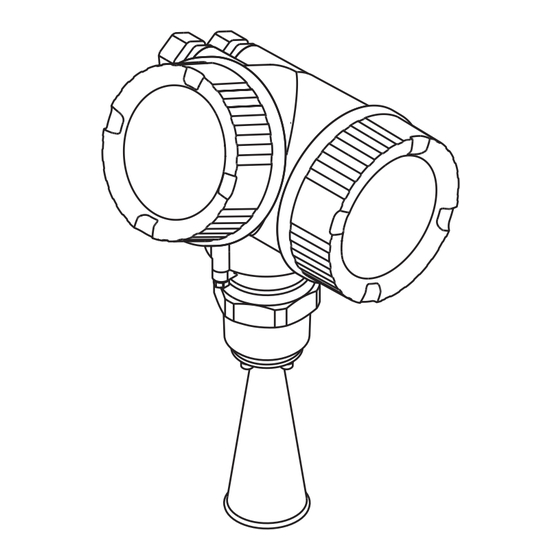
Micropilot FMR51, FMR52
FOUNDATION Fieldbus
Free space radar
These Instructions are Brief Operating Instructions; they are
not a substitute for the Operating Instructions pertaining to
the device.
Detailed information about the device can be found in the
Operating Instructions and the other documentation:
Available for all device versions via:
• Internet:
www.endress.com/deviceviewer
• Smart phone/tablet: Endress+Hauser Operations App
Solutions
Services
Advertisement
Table of Contents


Need help?
Do you have a question about the FOUNDATION Fieldbus Micropilot FMR51 and is the answer not in the manual?
Questions and answers