Hitachi CG 25EUAP (L) Service Manual
Engine brush cutter/grass trimmer
Hide thumbs
Also See for CG 25EUAP (L):
- Safety instructions and instruction manual (56 pages) ,
- Handling instructions manual (288 pages)
Table of Contents
Advertisement
Quick Links
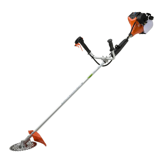
PRODUCT NAME
Hitachi Engine Brush Cutter/Grass Trimmer
CG 25EUAP (L)
Models
CG 25EUAP
CONTENTS
TROUBLESHOOTING GUIDE ---------------------------------------------------------------------------------------------- 1
1. Troubleshooting and correction ------------------------------------------------------------------------------- 1
REPAIR GUIDE ----------------------------------------------------------------------------------------------------------------- 3
1. Precautions on maintenance, inspection and repair ----------------------------------------------------- 3
2. Inspection criteria ------------------------------------------------------------------------------------------------ 3
• Repair flowchart ------------------------------------------------------------------------------------------------ 4
• Repair procedure ---------------------------------------------------------------------------------------------- 6
• Disassembly and reassembly ------------------------------------------------------------------------------- 9
• Lubrication points and type of lubricant -----------------------------------------------------------------21
• Screw tightening torque -------------------------------------------------------------------------------------22
• Confirmation after reassembly -----------------------------------------------------------------------------23
CG 25EUAP (L) for Europe
CG 25EUAP
LIST No.
CG 25EUAP: F084
Apr. 2016
CG 25EUAP (L) for the U. S. A. and Canada
Overseas Sales Division
C
Page
Advertisement
Table of Contents

Related Manuals for Hitachi CG 25EUAP (L)


Summary of Contents for Hitachi CG 25EUAP (L)
-
Page 1: Table Of Contents
LIST No. CG 25EUAP: F084 Apr. 2016 PRODUCT NAME Hitachi Engine Brush Cutter/Grass Trimmer CG 25EUAP (L) Models CG 25EUAP CONTENTS Page TROUBLESHOOTING GUIDE ---------------------------------------------------------------------------------------------- 1 1. Troubleshooting and correction ------------------------------------------------------------------------------- 1 REPAIR GUIDE ----------------------------------------------------------------------------------------------------------------- 3 1. Precautions on maintenance, inspection and repair ----------------------------------------------------- 3 2. -
Page 2: Troubleshooting Guide
TROUBLESHOOTING GUIDE 1. Troubleshooting and correction Problem Cause Corrective action The piston ring is stuck. Disassemble the engine and The connecting rod bearing is stuck. replace the faulty part. A valve is damaged. Replace the faulty part. Starter handle The crank shaft cannot be The crank gear or cam gear is does not rotate. - Page 3 Problem Cause Corrective action The fuel filter is clogged. Clean or replace the part. The engine stalls. Loose nuts Repair the parts. Worn push rod Valve Worn valve clearance is Worn pivot Replace the faulty part. extended. Starts, but when Worn rocker arm it accelerates…...
-
Page 4: Repair Guide
REPAIR GUIDE This section describes repair, focusing on parts that may require frequent repair according to the table in "TROUBLESHOOTING GUIDE." 1. Precautions on maintenance, inspection and repair • Never place fuel near a source of fire because the fuel is inflammable. •... -
Page 5: Repair Flowchart
Repair flowchart Piston ring is damaged. Replace. Pull the starter handle. Piston or cylinder is stuck. Replace. Check whether there is compression and the handle can Needle bearing on connecting rod is damaged. Replace. be pulled. Ball bearing is stuck. Replace. - Page 6 Check that the engine speed increases by pulling the throttle lever. Cylinder exhaust port or muffler is clogged with The speed does Clean. carbon. not increase. Cleaner element is clogged. Clean. Inspect and Valve clearance is extended. adjust. Carbon accumulated on a sealed valve surface. Clean.
-
Page 7: Repair Procedure
Repair procedures WARNING: Be sure to stop the engine before disassembly. [Bold] numbers in the description below correspond to the item numbers in the parts list and exploded assembly diagram for the Model CG 25EUAP. 1. How to check for sparks by the spark plug CAUTION: •... - Page 8 3. Electric wiring The figure below shows the electric wiring. (1) Connect the Stop Cord [126] to the Ignition Coil [125], and then connect the Earth Cord [124] to the Ignition Coil [125] with the Bolt M4 x 18 [123]. (2) Connect the two cords of the Stop Switch [164] or Stop Switch Comp.
- Page 9 5. Adjusting the valve clearance CAUTION: Be sure to adjust the valve clearance with the engine sufficiently cooled down. (1) Remove the two Screws [101] and upper Screw M4 x 25 [87] fixing the Recoil Starter [85], and then remove the Engine Cover [102] or [104]. (2) Remove the Bolt M5 x 20 [115], and then remove the Fan Case [112].
-
Page 10: Disassembly And Reassembly
Disassembly and reassembly 1. Fan case (1) Disassembly Remove the Bolt M5 x 20 [115] and Screw [101], and then remove the Fan Case [112]. Next, remove Pipe Holder (A) [108], Anti Vibe Rubber (A) [107], Pipe Holder (B) [109], and Anti Vibe Rubber (B) [110] in this order. - Page 11 2. Muffler ass’y (1) Disassembly Loosen the Bolts M5 x 40 [1], and then remove the Muffler Heat Cover [2] or [8], Muffler [7] or [9], Muffler Gaskets (A) [10], and Wind Guide Plate (B) [11]. (2) Reassembly Wipe off any carbon from the exhaust inlet and outlet of the Muffler [7] or [9], and then mount the removed parts in the order shown in the figure below.
- Page 12 3. Cleaner, carburetor and insulator (1) Disassembly Loosen the Cover Fixing Bolt [82], and then remove the Cleaner Cover [81] and Cleaner Element [80]. Loosen two Screws M5 x 68 [76], and then remove the Cleaner Body [72], Carburetor [26], and other parts.
- Page 13 4. Ignition coil and spark plug cap (1) Disassembly Loosen the Bolt M4 x 18 [123], and then remove the Ignition Coil [125]. To remove the Spark Plug Cap [16], add a drop of oil into the Spark Plug (TORCH CMR5H) [18] hole in the Spark Plug Cap [16], move the high-voltage cord back and forth to spread the oil, and then slowly pull out the Metal Fitting of Plug Cap [17] so that it is not extended.
- Page 14 6. Starter pulley ass’y, clutch ass’y and magneto rotor (1) Disassembly To remove the starter pulley, lightly hit the starter pulley to turn it counterclockwise while holding the Magneto Rotor [122]. To remove the Clutch [119], loosen the two Step Bolts [117]. To remove the Magneto Rotor [122], remove the Fly Wheel Nut [121], and then use the special magneto rotor assembly remover to pull out the Magneto Rotor [122].
- Page 15 7. Cylinder, rocker arm and valve (1) Disassembly Loosen three Bolts M4 x 10 [27], and then remove the Cylinder Head Cover [28]. If the Cylinder Head Cover [28] cannot be easily removed, use a plastic hammer to lightly hit the side of the Cylinder Head Cover [28].
- Page 16 • Cylinder, rocker arm and valve [12] [13] [12] [14] [15] [27] [13] [28] [29] [34] [30] [38] [35] [31] [41] [36] [32] [40] -15-...
- Page 17 8. Piston and piston ring (1) Disassembly Use long-nose pliers to remove the Circlip [52]. Pull out the Piston Pin [53], and then remove the Piston [51]. Remove the 1st Ring [48] and 2nd Ring [49] while opening their slits. The Oil Ring [50] consists of one expander and two scrapers.
- Page 18 9. Crank case ass’y (1) Disassembly Loosen the three Bolts M4 x 16 [47], and then remove the Cover Pump [46], Inner Rotor [44], Outer Rotor [45], and Base Pump [43]. Loosen the six Bolts M4 x 18 [65] to separate the Crank Case FW [59] from the Crank Case ST [64], and then remove the Crank Shaft Gear [58] and Cam Shaft [55].
- Page 19 10. Shaft unit (1) Disassembly • Loosen the Bolt M5 x 12 [182] and Bolt M5 x 30 [187], and then detach Gear Case Ass'y (S) [180] from the Main Pipe [229]. • Pull out the Drive Shaft [230] from Gear Case Ass'y (S) [180] side of the Main Pipe [229]. (2) Reassembly •...
- Page 20 11. Mounting the handle (1) Model CG 25EUAP • Position Handle Holder (B) [188] so that the distance between the engine side end of the Main Pipe [229] and the engine side end of Handle Holder (B) [188] is 400 mm. Then secure Handle Holder (C) [190] by tightening the two Bolts M6 x 25 [191] evenly.
- Page 21 (2) Model CG 25EUAP (SL) • Set the two Throttle Collars [201], Throttle Lever Ass'y [199], Grip [200], and Handle Clamp [203] around the Main Pipe [229]. Adjust the distance between the engine side end of the Main Pipe [229] and the Handle Clamp [203] to 90 mm.
-
Page 22: Lubrication Points And Type Of Lubricant
Lubrication points and type of lubricant Apply specified grease to the following parts. Grease Registered part name Net weight Code No. Hitachi Power Tool Grease No. 2 (30 g) 30 g 939301 Multemp PS No. 2 Grease (PS No. 2) (2.5 kg) 2.5 kg... -
Page 23: Screw Tightening Torque
Screw tightening torque Location Screw, bolt, or nut Quantity Tightening torque Recoil Starter [85] Seal Lock Screw M4 x 25 [87] 2.0 to 3.0 N•m Recoil starter Starter pulley 9 to 12 N•m Hex. Socket Hd. Bolt Ignition Coil [125] 2.5 to 4.5 N•m (W/Washers) M4 x 18 [123] Electric... -
Page 24: Confirmation After Reassembly
Confirmation after reassembly 1. Check the following before starting the engine. (1) Confirm that all fastening screws, bolts, and nuts are properly tightened. (2) Confirm that there is no gas leaking from any part of the engine section. (3) Confirm that the crank shaft rotates and there is compression when pulling the starter handle. (4) Perform priming ten times and then confirm that the priming pump is full of fuel. - Page 25 LIST NO. F084 ENGINE ENGINE GRASS TRIMMER 2016 · 4 · 22 Model CG 25EUAP (E1)
- Page 26 CG 25EUAP - 2 - 4 - 16...
- Page 27 CG 25EUAP 239 240 - 3 - 4 - 16...
- Page 28 PARTS CG 25EUAP ITEM CODE NO. DESCRIPTION REMARKS USED 6600652 HEX. SOCKET HD. BOLT (W.WASHER) M5 X 40 6600654 MUFFLER HEAT COVER FOR USA,CAN 6600989 SCREW M4 FOR USA,CAN 6600988 EXHAUST PIPE FOR USA,CAN 6600987 EXHAUST PIPE GASKET FOR USA,CAN 6600986 SPARK ARRESTER FOR USA,CAN...
- Page 29 HEX. SOCKET HD. BOLT (W/WASHERS) M5 X 20 6600686 ANTI VIBE RUBBER (A) 6600684 PIPE HOLDER (A) 6600685 PIPE HOLDER (B) 6600687 ANTI VIBE RUBBER (B) HITACHI LABEL 6600679 FAN CASE 6600680 FAN CASE FOR USA,CAN 6600683 RETAINING RING 4 - 16...
- Page 30 PARTS CG 25EUAP ITEM CODE NO. DESCRIPTION REMARKS USED CAUTION MARK 6600690 HEX. SOCKET HD. BOLT (W/WASHERS) M5 X 20 6600681 CLUTCH SHAFT 6600661 STEP BOLT 6600662 BENT WASHER 8 6600663 CLUTCH 6600664 CLUTCH WASHER (B) 6600658 FLY WHEEL NUT 6600655 MAGNETO ROTOR 6600659...
- Page 31 PARTS CG 25EUAP ITEM CODE NO. DESCRIPTION REMARKS USED 6600858 HOLDER (B) FOR EUROPE 6600859 NUT COVER FOR EUROPE 6600860 U-NUT (LEFT HAND) M10 FOR EUROPE 6600854 HEX. SOCKET HD. BOLT (W/SP.WASHER) M5 X 30 6600796 HANDLE HOLDER (B) EXCEPT FOR (L) 6601298 HANDLE HOLDER RUBBER EXCEPT FOR (L)
- Page 32 PARTS CG 25EUAP ITEM CODE NO. DESCRIPTION REMARKS USED 6601299 GUARD FOR EUROPE 6601222 GUARD FOR EUROPE (L) 6601223 GUARD HOLDER FOR EUROPE (L) 6601300 COVER GUARD (EU) FOR EUROPE 6601301 TAPPING SCREW D4 X 12 FOR EUROPE 6601302 KNIFE FOR EUROPE 949554 NUT M4 (10 PCS.)
Need help?
Do you have a question about the CG 25EUAP (L) and is the answer not in the manual?
Questions and answers