
Related Manuals for Delta M125HV 113


Summary of Contents for Delta M125HV 113
- Page 1 Grid-tie Transformerless Solar Inverter M125HV_113 Operation and Installation Manual English 繁體中文 www.deltaww.com...
-
Page 3: Table Of Contents
Contents ......... . . 1 Safety . - Page 4 4.3 Delta Function Setting ........
- Page 5 Figure ......Figure 2-1: M125HV_113 components ......Figure 2-2: DC wiring box components .
- Page 6 ....... . . Figure 4-1: Front Panel Display ......Figure 4-2: DSS Commission setting .
- Page 7 ... . . Figure A-8: SPD wiring of wires with spare parts refer DIN rail manual ....Figure A-9: Install the SPD and shield cover to the track .
-
Page 8: 1 Safety
DELTA ELECTRONICS, INC. Service engineers and end users may not divulge the information contained herein or use this manual for purpose other than those strictly connected with correct use of the product. -
Page 9: General Safety
This user manual provides important instructions for Delta grid-tie transformerless solar inverter. The product is designed, tested, verified, and certified according to international safety requirements, certifications, and standards but precautions must be observed when installing and operating the product. -
Page 10: Symbols
Safety 1.2.2 Symbols This section describes the definition of the symbols in this manual. In order to prevent both personal injury and property damage, and to ensure long-term operation of the product, please read this section carefully and follow all the safety instructions while you use the product. DANGER! - This warning indicates an immediate hazard which will lead to death or serious injury. - Page 11 Safety INFORMATION - An exclamation mark enclosed in a double circle indicates additional important information is contained in the following section and the user should follow the instructions to prevent any hazards. DANGER : ELECTRICAL HAZARD!! - This warning indicates an immediate electrical hazard that unheeded can lead to death or serious injury.
-
Page 12: 2 Introduction
The user manual is valid for the following device types: • M125HV_113 • DC Wiring Box This user manual must be followed during installation, operation, and maintenance. DELTA reserves the right to make modifications to the content and technical data in this user manual without prior notice. -
Page 13: Product Overview
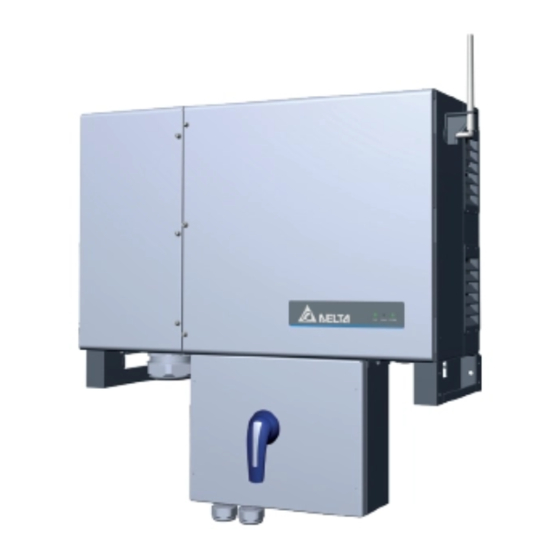
④ ⑤ ⑥ Figure 2-1: M125HV_113 components Table 2-1: M125HV_113 packing list M125HV_113 Object Description Delta Solar Inverter Solar inverter Wall mounting bracket Mounting Bracket (Material: Aluminum/Thickness: 3mm) Important instructions for solar inverter. Safety instructions should be followed User Manual... - Page 14 Introduction The components of DC Wiring Box is shown as Figure 2-2. ① ② ③ ④ ⑤ Figure 2-2: DC wiring box components Table 2-2: DC wiring box packing list DC Wiring Box for M125HV_113 Object Description DC Wiring Box For DC cable wiring The Instruction to provide the information of safety, Quick Installation Guide...
- Page 15 Introduction SUB_1G Antenna (optional) Air Outlets (filter) Rating Label Foot Air Inlets(filter) / Smart Fans 3 " gland for AC Wiring 28.9 mm gland DC Switch RS-485 for DC Wiring communications port, 1.1" Trade Size Opening Tools can be placed in the foot. Figure 2-3: Overview...
- Page 16 Introduction Figure 2-4 shows the rating label of M125HV_113, and Table 2-3, defines the symbol markings on this label. Manufacturing location: No. 1688 Jiangxing East Road, Wujiang Economic Development Zone Suzhou City, 215200 Jiangsu Province, P.R. China Solar Inverter ( 太陽能變流器...
- Page 17 Introduction Figure 2-5: External/ internal view...
- Page 18 Introduction ⑬ ⑦ ⑮ ⑪ ② ⑩ ⑥ ⑫ ⑭ ⑤ ⑤ ① ⑯ ⑧ ③ ④ ⑨ Figure 2-6: Layout Table 2-4: Layout description Component Component NO. Component 3” cable opening for AC Wiring N3U_SB1 Internal fan 2 AC terminal Communication port Din rail for AC SPD (optional)
-
Page 19: 3 Installation
Installation 3 Installation CAUTION ! - In some locations, mounting the inverter in direct sunlight may cause the inverter to enter a thermal derating mode. To eliminate this concern, a shade structure over the inverter chassis may be necessary. WARNING ! - Do not install the unit near or on flammable surfaces. -
Page 20: Unboxing & Review
Installation 3.1 Unboxing & Review Unpacking the M125HV_113, please follow the order of Figure 3-1. It could be transported by 2 people (Figure 3-2) or crane (Figure 3-3). Need more than two people to stand up. Figure 3-1: The step to unpacking the inverter... - Page 21 Installation Prohibit to force with fan shutter. Figure 3-2: Handle position for handling Please lock screw (0.5N•m) plugs or keep steel rings on the case after installation to avoid water inflow. The required bolt size is M12. Hoisting Hook Figure 3-3: Attaching the Hoisting hooks...
-
Page 22: Installation Steps
CAUTION ! Protection cover To avoid malfunction of inverter caused by extreme weather (ex: snow, hail…etc) or non-proper installation/ maintenance, an additional protection cover is strongly recommended to be installed by DELTA. For more details, please contact local service team. -
Page 23: Vertical Wall Mount
Installation 3.2.1 Vertical Wall Mount Refer to Figures 3-6 through Figures 3-10. 1. Ensure the surface to which the unit is to be mounted is sufficiently strong enough to carry the weight. 2. Orient the wall bracket horizontally (perpendicular to the floor), with the large plate at the bottom, and mark required mounting hole locations per Figure 3-6. - Page 24 Installation 612 mm 606 mm 10.5 19.2 mm 102 mm 306 mm 510 mm 950 mm Figure 3-6: Mounting bracket dimensions Wall > 94cm > 40cm > 65cm > 129cm > 61cm Inverter #1 Inverter #2 > 190cm > 95cm >...
- Page 25 Installation >380mm >500mm >500mm >1000mm height * height * * For wall mount installation, make sure it is high enough to have sufficient space for wiring. Back to Back When M125HV mounted back to back, clapboards must be installed on both sides. >...
- Page 26 Installation After installing the reinforce brackets on the foots (Figure 3-9), secure the reinforce brackets to the wall with two screws (M10) per Figure 3-10. * Screw torque required for assembling: 15 N•m Figure 3-9: Install the unit on the foots Figure 3-10: To secure inverter reinforce brackets to wall-mounting bracket...
- Page 27 Installation Figure 3-11: Permitted mounting positions Figure 3-12: Prohibited mounting positions O : Permitted / X : Prohibited...
-
Page 28: Dc Wiring Box Installation
Installation 3.3 DC wiring box installation After mounting M125HV, please open the front cover of the DC wiring box before install the wiring box on the inverter. (Figure 3-13) * Screw torque required for assembling: 4.4 N•m Figure 3-13: Open the front cover of the DC wiring box Pass through the DC cable from M125HV to DC wiring box, Use 4 M5 hex nut to fix the DC wiring box on the M125HV inverter. - Page 29 Installation Use M8 hex nut to tighten the cable on terminal. * M8 Nut torque: 14.7 N•m Figure 3-15: Internal DC cabling...
-
Page 30: Door
Installation 3.4 Door In order to guarantee proper long-term operation of the inverter, procedures in Section 5.1 must be followed. For the first time installation, only need to open the AC side (left) door for wiring. * Screw torque: 4.4 N•m Figure 3-16: First installation of M125HV_113 INFORMATION - Use Hexagon Driver or other proper tool to untighten door screws. -
Page 31: Electrical Installation For Ac Wiring
Installation 3.5 Electrical Installation for AC Wiring DANGER : ELECTRICAL HAZARD!! - To avoid shock hazard during cabling, insure any live grid connections are removed from the inverter. DANGER! - It is forbidden to open both doors at the same time. WARNING ! - Code compliance is the installer's responsibility. -
Page 32: Ac Grid Types And Connections
Installation 3.5.1 AC Grid Types and Connections ATTENTION The default AC Grid connection is 3Ø-3W. It can also connect 3Ø-4W without Neutral (N). The inverter will operate from the following grid connections without need of an external transformer: TNC system TNC-S system 347/600V 347/600V... -
Page 33: Ac Side -Prewire Set-Up
Installation Conductor cross-section: Cu: 50 ~ 185 mm Al: 95 ~ 185 mm outer jacket Figure 3-17: Size of AC conductors Φ10.5 mm <31 mm AC Terminal (tin-plated) PE Connection (Nickel-plated) Conductor Compatible Lug Conductor Compatible Lug Cu(Tin-Plated) Cu(Tin-Plated) Cu(Nickel-Plated) Pure Cu Pure Cu Aluminum (Tin-Plated)*... -
Page 34: Ac Wiring
Installation 3.5.5 AC Wiring Refer to Figure 3-17 in Section 3.5 for the procedure to prepare AC conductors for connection to the AC terminals. Ensure the AC conductors used are sized to the correct ampacity per NEC or other local code. Refer to Figure 3-17. AC terminal After inserting conductor, torque... - Page 35 Installation Torque 0.8 N • to fix the screws Figure 3-20 : AC gland assembling CAUTION ! The cable gland is suitable for multi-core cable, if wiring is using single-core cable with 3” flexible metal conduit, please follow below suggestions to avoid water intrusion: a.
-
Page 36: Electrical Installation For Dc Wiring
Installation 3.6 Electrical Installation for DC Wiring DANGER : ELECTRICAL HAZARD!! - PV array converts sunlight into electric power with high DC voltage and high DC current which can cause dangerous electrical shock hazard! - Use an opaque material to cover the PV array before wiring or cabling. - Ensure the correct polarities are connected when DC cabling is applied. -
Page 37: Dc Wiring Preparation
Installation 3.6.1 DC Wiring Preparation Below is the procedure for preparing the DC conductors for connection to the DC terminals: • It is important to choose the proper size for DC cable. Refer to Figure 3-21. • The cross-sectional area for each DC conductor is 50~300 mm for Cu. -
Page 38: Dc Side -Prewire Set-Up
Installation 3.6.2 DC Side –Prewire Set-Up Prior to installing conductors on terminal complete the following procedure to make terminals ready for connections. For each of the DC terminals (PV+ / PV-): Tighten/Lose nuts with 19mm socket. If an electric socket is utilized insure the torque setting is low enough to NOT OVER-TORQUE the screw. -
Page 39: Equipment Grounding
Installation 3.7 Equipment Grounding To ground the inverter, please crimp the grounding wire to the ring terminal lug and fix it on the grounding point shown as figure 3-24. mounting torque: M6/ 7 N•m M10/ 25 N•m * Nut torque: M10/ 25 N•m * Nut torque: M6/ 7 N•m M10/ 25 N•m Figure 3-24: Mount the equipment grounding... -
Page 40: Antenna (Optional)
ATTENTION - Always keep nut and screws properly tightened on the case. Water leakage may cause serious damage. Contact DELTA service when lack for nut and screws. - Store the nut for spare usage. Antenna location Save the nut after antenna installed. - Page 41 Installation >20cm There must be no obstacles within 20 cm around the antenna. Keep antenna pointing upright. Figure 3-26: Attentions of installing antenna...
- Page 42 Installation Screw locations Put on the bracket from the top of Tighten the 3 M4 screws to antenna antenna until matching screw holes. bracket with 0.98 N • m torque. Figure 3-27: Attentions of installing antenna bracket ATTENTION - Please refer Data Collector manual for connection of Data Collector. https://mydeltasolar.deltaww.com/?p=product_manual...
-
Page 43: Communication Module Connections
Installation 3.9 Communication Module Connections The communication module of M125HV_113 is shown in Figure 3-28. It provides VCC, RS-485, dry contact, EPO, and Digital Input terminals for use in various applications. Details for each are presented below. There's a 12VDC source between VCC & GND for use with external device. V1 *1 &... -
Page 44: Accessing The Communication Module
Installation 3.9.1 Accessing the Communication Module The communication module consists of an assembly with a PCB and a plastic carrier. It is located in a slot through the bottom of the chassis. It is accessed from the bottom exterior of the chassis. The carrier is secured to the chassis by two self-retaining screws. -
Page 45: Connection
Installation 3.9.2 RS-485 Connection The pin definition for the RS-485 terminal block is shown in Table 3-1. - Pins 1 and 2 provide a 12VDC bus for use with accessories. (If use of 12VDC bus is necessary, place switch 1 in ON position.) - Pins 3 and 5 are both connected to the DATA+ input. - Page 46 Installation Terminal Resistor (Last inverter in chain must have Switch 2 in ON position.) RS485/USB RS485/RS232 Figure 3-31: Multiinverter connection illustration Table 3-2: Vcc and Bus Termination switch settings Switch 1 Terminal Resistor ON Terminal Resistor OFF...
-
Page 47: Epo Function & Digital Input
Installation 3.9.3 EPO Function & Digital Input The communication Module has an emergency power off function (EPO). Users can customize EPO function in APP or Delta Solar System (DSS). V1 K0 K1 K2 K3 K4 K5 K6 Figure 3-32: EPO function terminal block Once enabled, the EPO function can be used to turn off the inverter via a NO relay contact connected across terminal [V1 &... -
Page 48: Dry Contact Connection
Installation 3.9.4 Dry Contact Connection M125HV_113 provides a dry control contact pair that may be used to control external devices based on the status of operation of the inverter. The terminal block for this function is shown in Figure 3-33. The terminals marked in the figure identify the dry contact connection. -
Page 49: 4 Commissioning
Commissioning 4 Commissioning CAUTION : HOT SURFACES, DO NOT TOUCH! - Use care to avoid hot surfaces when operating the product! - Do not perform any task until the unit cools down or appropriate personal protection gear is worn. 4.1 Display Operation Introduction M125HV_113 with 3 LEDs allow visual display of the inverter’s data and status as shown in Figure 4-1. -
Page 50: Auto Id Commission
Commissioning 4.2 Auto ID Commission The Auto ID function can set all inverter IDs by DSS through (Delta Solar System) RS-485 or set by MyDeltaSolar APP through Wi-Fi, please refer to chapter 4.3 for operation manual. 4.2.1 Commission Setting (DSS) ①... -
Page 51: Scan Inverter
Commissioning 4.2.2 Scan inverter ① Click “Auto ID ”. ② Enter numbers of inverters and click “Scan”. ① ② Figure 4-3: Steps of scanning inverters... -
Page 52: Set Id
Commissioning 4.2.3 Set ID ① The serial number of the successfully scanned device will be displayed, the default ID can be changed. ② After ID setting is completed, click “Set ID”. ② ① Figure 4-4: Steps of ID setting... -
Page 53: Set Country
Commissioning 4.2.4 Set Country ① Click to select the country of inverter. ② Click “Set”. ① ② Figure 4-5: Steps of country setting... -
Page 54: Synchronize Time
Commissioning 4.2.5 Synchronize time Click “Sync Clock ” to Synchronize time. Figure 4-6: Steps of time synchronization... -
Page 55: Delta Function Setting
Commissioning 4.3 Delta Function Setting Delta offers two setting tools: DSS (Delta Solar System Software) and APP (MyDeltaSolar) Function Active power control Q(U) control (volt-var control) P-F control (watt-frequecy control) Q by night(Q setting 24/7) P(U) control (volt-watt control) Anti-PID Fixed cosφ... -
Page 56: 5 Maintenance
Maintenance 5 Maintenance Please check the unit regularly. If there are any impaired or loose parts, please contact your solar installer. Ensure that there are no fallen objects in the path of the heat outlet. WARNING ! - Please make sure AC and DC power are both off prior to any maintenance procedures to avoid risk of electric shock. - Page 57 Maintenance M125HV_113 * Show the AC side door. AC side (left) LED side (right) ATTENTION - After opening the door, please make sure the door is fixed by hexagon driver to avoid strong wind breaking it. Figure 5-1: Open the door...
-
Page 58: Close The Door/Cover
Maintenance DC combiner box Figure 5-2: Open the cover of DC combiner box 5.1.3 Close the Door/Cover 1. Make sure that the terminals or viewable live parts are clean without sundries, dust even liquid. 2. All protection covers are installed well. 3. -
Page 59: Replacement Of Surge Protection Devices (Spd)
Maintenance 5.2 Replacement of Surge Protection Devices (SPD) M125HV_113 have the surge protection device (SPD) at both AC and DC side as shown in Figure 5-4. Table 5-1 summarizes the specifications of AC and DC SPD. Figure 5-4: AC and DC SPD modules Table 5-1: SPD Specifications Description Value... - Page 60 Maintenance • Accessing the door 1. Follow Section 5.1.1 to disconnect M125HV_113 from Voltage Sources. 2. Follow Section 5.1.2 to open M125HV_113 door. • Changing the SPD modules - use the following procedure: The AC and DC SPD units are located as shown in Figure 5-5. •...
- Page 61 Maintenance AC side door LED side door Confirm the replacement position, only the left door can be opened on the AC side (left) door, either the DC side (right) door can only be opened on the right side. It is forbidden to open Both doors at the same time.
- Page 62 Maintenance AC SPDs * A/G: Screw torque 0.8N•m Figure 5-6: Remove wirings as connectors of AC SPD DC SPDs * A/G: Screw torque 0.8N•m Figure 5-7: Remove wirings as connectors of DC SPD...
-
Page 63: Replace Internal String Fuse
Maintenance 5.3 Replace Internal String Fuse The combiner box utilize standard 60mm x 196mm PV fuses and associated at both positive and negative side. Because of the TL design, both strings are floating and not connected to ground. Standard fuse of M125HV_113 is 250A, the specifications for the required fuse and fuse brands used in the factory are listed below. - Page 64 Maintenance M125HV_113 has fuses for both and negative side inside the DC combiner box, please follow Figure 5-8 to replace the fuse. * please avoid drop the fuse to the floor, if it drop down please change the new fuse for the combiner box.
-
Page 65: Smart Fans Replacement And Filter Cleaning
Maintenance 5.4 Smart Fans Replacement and Filter Cleaning M125HV_113 is provisioned with processor-controlled "smart fans" for cooling of the electronics. This section provides procedures for cleaning filters associated with these fans, and instructions for field replacement of the fans. The fans utilized have high reliability ratings and coupled with use of processor controls provide a "smart"... -
Page 66: Location Of Failure Fan
Periodic fan and filter cleaning is required to insure long life and reliability. - The time period between cleanings depends on the quality of the environment. - Under normal duty use, Delta recommends smart fans and filters be cleaned every 4 months - For very dusty locations, it may be necessary to clean the fans and filters quarterly or monthly. -
Page 67: Power Module (Pm) Fan Tray
Maintenance 5.4.2 Power Module (PM) Fan Tray The inverter electronics are convection cooled. The primary equipment used for this function consists of a fan tray located in a plenum within the inverter. The PM electronics are isolated, and heat is transferred to the plenum airflow via a large heatsink. - Page 68 Maintenance * Screw torque required for assembling: 0.8N•m ① ② * Screw torque required for assembling: 0.8N•m ③ snap-fit ④ * Screw torque required for assembling: 0.6N•m Figure 5-11: Disassembling fan tray from PM chassis...
-
Page 69: Internal Fan 1
Maintenance 5.4.3 Internal Fan 1 When used, the LED side (right) compartment is provisioned with a single fan module. (See Figure 5-12, 5-13, 5-14, 5-15) If the warrning "Fan Fail- Internal F00" show on the DSS / APP, please follow the procedure below to remove Internal Fan 1. - Page 70 Maintenance * Screw torque required for assembling: 0.8 N•m Figure 5-14: Take off the internal fan 1 * Screw torque required for assembling: 0.6 N•m Figure 5-15: Replace with a new fan...
-
Page 71: Internal Fan 2
Maintenance 5.4.4 Internal Fan 2 When used, the AC side compartment is provisioned with a single fan module. (See Figure 5-16, 5-17, 5-18, 5-19) If the warrning "Fan Fail- Internal F01" show on the DSS / APP, please follow the procedure below to remove Internal Fan 2. (1) Remove the shield cover. - Page 72 Maintenance Figure 5-18: Take off the internal Fan 2 * Screw torque required for assembling: 0.6N•m Figure 5-19: Replace with a new fan...
-
Page 73: Commissioning
Maintenance 5.5 De-Commissioning When necessary to remove the inverter from active operation for maintenance or replacement, follow the instructions below. DANGER : ELECTRICAL HAZARD!! - Ensure DC and AC cables are always de-energized during De-commissioning to avoid Shock Hazard! CAUTION : HOT SURFACES - The surface of the inverter may be hot to cause injury, ensure the temperature is in the proper range before De-commissioning. -
Page 74: 6 Error Message And Trouble Shooting
Error Message and Trouble Shooting 6 Error Message and Trouble Shooting While Delta Electronics endeavors to build electronic products to very high standards of reliability, there will arise instances where the inverter may not operate properly. When such a condition is encountered, please follow the instructions in the Troubleshooting Guide (Tables 6-1, 6-2, and 6-3) to attempt to clear the fault. -
Page 75: Fault Codes (Inverter Fault)
Error Message and Trouble Shooting 6.2 Fault Codes (Inverter Fault) Table 6-2A: Fault Codes (inverter fault) & Messages Message Description Action Injection Contact customer service for Utility waveform is abnormal technical support (F01, F02, F03, F04) Temperature One of inner ambient NTC and Check the installation ambient and High inverter module NTCs is over... - Page 76 Error Message and Trouble Shooting Table 6-2B: Fault Codes (inverter fault) & Messages Message Description Action 1. Power line is disconnected Iac Unbalance inside the inverter Check the connection in AC terminal 2. Current feedback circuit is (F26) defective Contact customer service for RCMU Fault RCMU circuit is disconnected (F27)
-
Page 77: Warning Codes (Field Warning)
Error Message and Trouble Shooting 6.3 Warning Codes (Field Warning) Table 6-3A: Warning Codes (Field warning) & Messages Message Description Action 1. Check the installation ambient and environment 2. Check Grid Code & Grid setting 1. Over temperature 3. Check the utility frequency on the inverter 2. -
Page 78: 7 Technical Information
Technical Information 7 Technical Information 7.1 Technical of M125HV_113 Table 7-1A: Specifications Model M125HV_113 DC Input Occasionally Max. voltage 1600V * 860 – 1500V Operating voltage range 860 – 1350V * MPP voltage range Rated voltage 1050V MPP tracker Max. operating current 150A Max. - Page 79 Technical Information Table 7-1B: Specifications Model M125HV_113 Efficiency Peak efficiency >99 % 98.7 % Euro efficiency Information RS-485 (Delta / Sunspec) Communication SUB_1G (optional) (Grid, Alarm, COMM.) Indicator Regulation Enedis-PRO-RES_64E GB/T 19964: LVRT IEC 62109-1/-2 UTE C 15-712-1 IEC 61727...
- Page 80 Technical Information If the input voltage is higher than 1350V, the inverter may derate the output power. The relationship between the input voltage and the output power derating is shown in Figure 7-1. Input Voltage Derating of M125HV_113 Output voltage at 600Vac P/Pn(%) Pn=125kW 100%...
- Page 81 Technical Information Power Derating Curve with Ambient Temprature Output voltage at 600Vac PF=1 P/Pn(%) Pn=125kW 110% 100% 90 % 80 % 70 % 860V 60 % 1050V 1250V 50 % 1350V 40 % 30 % 20 % Ambient Temperature (°C) Figure 7-2: Power Derating Curve with Ambient Temprature (PF=1)
- Page 82 Technical Information Power Derating Curve with Ambient Temprature Output voltage at 600Vac PF=0.9 P/Pn(%) Pn=125kW 110% 100% 90 % 80 % 70 % 860V 60 % 1050V 1250V 50 % 1350V 40 % 30 % 20 % Ambient Temperature (°C) Figure 7-3: Power Derating Curve with Ambient Temprature (PF=0.9)
- Page 83 Technical Information Apparent Power Derating Curve with Ambient Temprature Output voltage at 600Vac PF=1 S/Sn(%) Sn=125kVA 110% 100% 90 % 80 % 70 % 860V 60 % 1050V 1250V 50 % 1350V 40 % 30 % 20 % Ambient Temperature (°C) Figure 7-4: Apparent Power Derating Curve with Ambient Temprature (PF=1)
- Page 84 Technical Information Apparent Power Derating Curve with Ambient Temprature Output voltage at 600Vac PF=0.9 S/Sn(%) Sn=125kVA 112% 110% 100% 90 % 80 % 70 % 860V 60 % 1050V 1250V 50 % 1350V 40 % 30 % 20 % Ambient Temperature (°C) Figure 7-5: Apparent Power Derating Curve with Ambient Temprature (PF=0.9)
- Page 85 Technical Information Power Derating Curve with Input Voltage Output voltage at 600Vac PF=1 P/Pn(%) Pn=125kW 110% 100% 90 % 80 % 70 % AMB_50°C 60 % AMB_40°C AMB_<25°C 50 % 40 % 30 % 20 % 10 % 1250 1350 1450 1550 1150...
- Page 86 Technical Information Power Derating Curve with Input Voltage Output voltage at 600Vac PF=0.9 P/Pn(%) Pn=125kW 110% 100% 90 % 80 % 70 % AMB_50°C 60 % AMB_40°C AMB_<25°C 50 % 40 % 30 % 20 % 10 % 1250 1350 1450 1550 1150...
- Page 87 Technical Information Efficiency of M125HV_113 Output voltage at 600Vac Efficiency(%) Pn=125kW 100% 860V 1050V 1250V 1350V 100% Output Power (%) Figure 7-8: Efficiency Curve...
-
Page 88: Appendix A: Installation Of Din Rail Spd (Optional)
Appendix A: Installation of DIN Rail SPD (Optional) Appendix A: Installation of DIN Rail SPD (Optional) M125HV_113 support the spare parts of DC/AC DIN rail SPDs with typeI and typeII. - Exchange DC SPD, there are some spare parts for exchange SPD, such as PE wiring, track and nuts are shown in Figure A-2. - Page 89 Appendix A: Installation of DIN Rail SPD (Optional) DC DIN Rall SPD 120mm MAX. 35mm DIN Rail Mountable Figure A-1: DC DIN Rall SPD Select spare parts Figure A-2: DC SPD The step of exchange DIN rail SPD: 1. Open the shield cover. (Figure A-3) 2.
- Page 90 Appendix A: Installation of DIN Rail SPD (Optional) Figure A-3: Open the DC SPD shield cover DC SPDs * A/G: Screw torque 0.8N • m Figure A-4: Disassemble and remove two screws to remove DC SPD PCB...
- Page 91 Appendix A: Installation of DIN Rail SPD (Optional) Nut torque 4.4N • m Nut torque 4.4N • m Nut torque 2N • m Nut torque 2N • m Figure A-5: Lock track and Install...
- Page 92 Appendix A: Installation of DIN Rail SPD (Optional) AC DIN Rall SPD 55mm MAX. 108mm MAX. Figure A-6: AC DIN Rall SPD Select spare parts Figure A-7: AC SPD The step of exchange DIN rail SPD: 1. Open the shield cover. 2.
- Page 93 Appendix A: Installation of DIN Rail SPD (Optional) Remode signalling contactor Figure A-8: SPD wiring of wires with spare parts refer DIN rail manual * Nut torque required for assembling: 2 N • m Figure A-9: Install the SPD and shield cover to the track...
- Page 94 Appendix A: Installation of DIN Rail SPD (Optional) Figure A-10: Connect the spare parts of wring connectors AC SPDs Move the PCB SPD fignal to the Din rain SPD signal connector on the sheet metal. Figure A-11: Remove wring connectors...
-
Page 95: Appendix B: Assembly Note
Appendix B: Assembly Note Appendix B: Assembly Note ② ⑦ ⑥ ④ ③ ① ⑤ Appendix B-1: Assembly Note-1 Location Screw torque Filter 8.0 kgf-cm (0.8N•m) Fan Tray 8.0 kgf-cm (0.8N•m) 6 kgf-cm (0.6N• m) Screw Plug 5.0 kgf-cm (0.5N• m) Reinforce Bracket / Grounded Bracket 150 kgf-cm (15N•... - Page 96 Appendix B: Assembly Note ④ ⑤ ② ③ ⑥ ⑦ ⑧ ① Appendix B-2: Assembly Note-2 Location Screw torque 71 kgf-cm (7.0N• m) Grounding 254 kgf-cm (25N• m) AC Cover 8.0 kgf-cm (0.8N•m) Internal Fan 2 Cover 20 kgf-cm (2.0N•m) Internal Fan 2 Tray 6 kgf-cm (0.6N•m) Internal Fan 1 Cover 8.0 kgf-cm (0.8N•m)
- Page 97 Appendix B: Assembly Note ④ ⑥ ① ⑤ ② ⑥ ⑤ ③ Appendix B-3: Assembly Note-3 Location Screw torque Conductor cross-section Cu: 50 ~ 185 mm² AC terminal 254 kgf-cm (25N• m) Al: 95 ~ 185 mm² Communication cover 8.0 kgf-cm (0.8N•m) Communication port 20 AWG (0.5mm²) Crossbeam...
- Page 98 Appendix B: Assembly Note ⑤ ① ③ ② ② ④ Appendix B-4: Assembly Note-4 Location Screw torque Conductor cross-section Cu: 50 ~ 300 mm² DC terminal 459 kgf-cm (45N•m) Al: 120 ~ 300 mm² DC front cover 45 kgf-cm (4.4N•m) Internal DC cabling 150 kgf-cm (14.7N•...
- Page 99 三相併網型變流器 M125HV_113 操作手冊 English 繁體中文 www.deltaww.com...
- Page 100 Contents ......... . 1 安全規範...
- Page 101 4.3 Delta 功能設定 ..........
- Page 102 Figure ........圖 2-1: M125HV_113 內容物 ........圖...
- Page 103 ......... 圖...
- Page 104 ......圖 A-8: 雷擊保護裝置的配線請參考其產品說明書 ......圖...
-
Page 105: 1 安全規範
安全規範 1 安全規範 1.1 變流器資料 1.1.1 免責聲明 著作權~ DELTA ELECTRONICS, INC. - All rights reserved. 本說明書及產品供終端使用者使用。技術資料及內圖文皆為機密資料且不經 DELTA ELECTRONICS, INC. 許可,禁止複製翻印。 維修工程師及終端使用者禁止洩漏內涵之訊息及除以正確使用本產品以外的目的 使用本說明書。所有資訊若有變更,不另外通知。 DELTA ELECTRONICS, INC.針對以下情形造成的損害將不負任何責任及義務: (a)產品沒有恰當的安裝或維修 (b)產品未依照說明書正確使用 (c)產品於拆裝過程受損 1.1.2 適用對象 本說明書適用於針對安裝、試運行、實際操作、後續維護受過良好訓練的人以下 基礎及進階技巧為必需的。 ‧ 了解基礎電力、配線、電子元件及電子電路符號 ‧ 了解太陽能變流器如何運行及操作 ‧ 針對電子產品的安裝及試運行受過訓練 ‧ 針對安裝及使用電子產品的過程中會遇到的危險及風險受過訓練 ‧ 遵守本說明書及所有安全規範... -
Page 106: 安全概述
1.2 安全概述 重要安全指示:保存所有指示! - 請詳閱所有指示並保存本說明書以供後續使用。 為了避免人員受傷或其他損失及確保變流器長期運轉,在使用此產品前請務必詳閱 所有安全指示。 本說明書針對Delta併網型無變壓器太陽能變流器提供重要指示。本產品進行設計、 測試、驗證且經國際安全規範認證,但安裝及使用本產品前仍須做好防範措施。 本產品適用於室內及戶外。 注意:無電氣隔離 - 本產品需安裝外部隔離變壓器確保交流側與太陽能模組進行隔離。 - 本產品無附加變壓器, 為非電氣隔離型。 市電端與變流器間需加入外部變壓器。 請勿使用需接地(正極或負極)之太陽能板。 若使用了, 則本產品會以INSULATION (E34) 告警。 - L1, L2, L3 禁止連接至地。 1.2.1 使用條件 - M125HV_113 為單一MPP追蹤、無變壓器太陽能變流器,能將太陽能串列的變 動電流轉換成與市電頻率相同之三相交流能量並饋入市電。 - 所使用之太陽能模組需與變流器匹配。 - 太陽能面板之對地電容不可超過 20μF。 - 本產品僅可在經DELTA及市電業者許可之國家運行。... - Page 107 安全規範 1.2.2 標誌 本節說明本說明書會出現的標誌定義,為了避免人員受傷或其他損失及確保變流器 長期運轉,在使用此產品前請務必詳閱所有安全指示並遵守。 危險! - 此警語表示可能發生致死或嚴重傷亡的情形。 警告! - 此警語表示可能發生致死或嚴重傷亡的情形。 注意! - 此警語表示可能發生較輕微傷害的情形。 注意 - 此警語表示可能對資產或環境造成傷害。...
- Page 108 安全規範 資訊 - 進一步的資訊會經由雙圈驚嘆號指示。 這代表接續的內容將含有使用者該遵守的重要資訊以免造成任何傷害。 危險:觸電!! - 此警語表示可能會有造成嚴重傷亡的觸電可能。 注意:表面高溫,請勿觸碰! - 此警語表示當變流器運行時機體表面高溫,請待表面溫度下降後再進行 需接觸的工作。 - 等待圖示中所顯示的時間後再進行工作 - 設備接地導體...
-
Page 109: 2 產品介紹
產品介紹 2 產品介紹 M125HV_113 以最先進之高頻切換及低EMI技術設計而成,同時具有高效率及高 壽命的特點,亦適用於戶外。 注意:無電氣隔離 - 本產品無附加變壓器,為非電氣隔離型。 請勿使用需接地(正極或負極)之太陽能板。 若使用了,則本產品會以INSULATION (E34) 告警。 - L1, L2, L3禁止連接至地。 2.1 適用機種 本說明書適用以下機種: • M125HV_113 • 直流配線箱 安裝、運行及維護過程皆必須遵守本說明書。 DELTA保留在不另行告知的前提下修改內容及技術資料的權力。 危險! - 禁止同時打開左右兩扇門。... -
Page 110: 產品概述
產品介紹 2.2 產品概述 M125HV_113 內容物如圖2-1所示。 ① ② ③ ④ ⑤ ⑥ 圖2-1: M125HV_113 內容物 表2-1: M125HV_113 內容清單 M125HV_113 物件 數量 描述 DELTA太陽能變流器 太陽能變流器 將變流器掛起之壁掛架 壁掛架 (材質: 鋁 / 厚度: 3mm) 安裝及維運過程中務必參考本說明書中的 操作手冊 安全指示 六角板手 固定前蓋用門閂 壁掛支撐架 用於變流器兩側的壁掛支撐架 M8x16L 螺絲 用於固定壁掛支撐架... -
Page 111: 圖2-2: 直流配線箱內容物
產品介紹 直流配線箱內容物如圖2-2所示。 ① ② ③ ④ ⑤ 圖2-2: 直流配線箱內容物 表2-2: 直流配線箱內容清單 M125HV_113 直流配線箱 物件 數量 描述 直流配線箱 用於直流配線 快速安裝指南 提供安全信息的說明,安裝和規格 M5螺帽 用於固定直流配線箱至機器主體 M8螺帽 用於固定M125HV主體的直流纜線 M12螺帽 (加華司墊圈) 3組 用於固定直流配線... -
Page 112: 圖2-3: 外觀介紹
產品介紹 SUB_1G 天線 (選配) 出風口 (濾網) 產品標籤 腳座 入風口(濾網) / 智慧風扇 3" 交流輸出 28.9 mm 直流輸入 直流開關 RS-485 (1.1" Trade Size Opening) 腳座內可以置放工具 圖2-3: 外觀介紹... -
Page 113: 圖2-4: 產品標籤
產品介紹 圖2-4為產品標籤並配合表2-3針對特殊符號做解釋。 Manufacturing location: No. 1688 Jiangxing East Road, Wujiang Economic Development Zone Suzhou City, 215200 Jiangsu Province, P.R. China Solar Inverter ( 太陽能變流器 Model( 型號 M125HV_113 Part Number( 料號 RPI124M113000 產品內含射頻模組: DC Input( : 860 -1500Vdc, MPPT 860 -1350Vdc 輸入... -
Page 114: 圖2-5: 外部/內部結構
產品介紹 圖2-5: 外部/內部結構... -
Page 115: 圖2-6: 內部架構
產品介紹 ⑬ ⑦ ⑮ ⑪ ② ⑩ ⑥ ⑫ ⑭ ⑤ ⑤ ① ⑯ ⑧ ③ ④ ⑨ 圖2-6: 內部架構 表2-4: 內部架構內容 部件 部件 部件 3”交流輸出接頭 內部風扇 2 _SB1 交流端子 RS-485進線孔 軌道式交流側雷擊保護裝置安裝 (選配) 保險絲 28.9 mm 直流輸入接頭 SUB_1G 天線 (選配) 直流雷擊保護裝置... -
Page 116: 3 安裝
安裝 3 安裝 注意! - 本產品不建議安裝在直接日照曝曬處。 警告! - 請勿將本產品安裝在易燃表面附近。 - 請將本產品安裝於堅固且平順之表面。 - 變流器可能造成電磁干擾,不適合安裝於居家環境,或者需採取緩解措施。 本章節包含以下指示 1.機構安裝 2.電氣安裝 3.通訊安裝 圖3-5提供變流器詳細尺寸... -
Page 117: 拆箱與檢視
安裝 3.1 拆箱與檢視 請依照圖3-1所示進行拆封。 建議兩人以上進行作業(圖3-2)或以起重機搬運(圖3-3)。 建議兩人以上進行 扶正作業。 圖3-1: 開箱步驟... -
Page 118: 圖3-2: 搬動施力位置
安裝 搬動時,請勿施加 外力於風扇出風口 圖3-2: 搬動施力位置 請以扭力值 0.5N‧m 鎖附盲塞或保留吊環於變流器上, 以避免水流入洞口。(盲塞尺寸: M12) Hoisting Hook 圖3-3: 安裝吊掛鋼環... -
Page 119: 安裝步驟
安裝 3.2 安裝步驟 此機器設計支援壁掛式安裝,請參考3.2.1 章節。 牆面 牆面 牆面 步驟 步驟 步驟 安裝機器主體 安裝直流配線箱 進行配線 (參考章節3.2) (參考章節3.3) (參考章節3.5 & 3.6) 圖3-4: 安裝步驟 注意! Protection cover 為避免由於極端氣候(大雪, 冰雹…等)或不恰當的 安裝/維運所導致的變流器故障, 台達強烈建議安 裝額外的保護蓋,詳細細節請洽當地服務團隊。... -
Page 120: 直立壁掛式安裝
安裝 3.2.1 直立壁掛式安裝 請參考圖3-6至3-10說明 1. 首先請先確定產品安裝牆面足以承載產品重量。 2. 水平固定壁掛架(垂直於地板),並依照圖3-6所示標記安裝孔洞位置。 3. 鎖附6枚M10螺絲於壁掛架上。 4. 將產品放置於壁掛架上。 5. 將產品鎖附上2枚M10螺絲如圖3-10。 注意! - 該壁掛架為本產品專用,請勿使用其他壁掛架來搭配本產品使用。 - 使用6枚M10螺絲將壁掛架固定牆上。(至少5枚) 900 mm 360.8 mm 964 mm 圖3-5: 變流器尺寸... -
Page 121: 圖3-6: 壁掛架尺寸
安裝 612 mm 606 mm 10.5 19.2 mm 102 mm 306 mm 510 mm 950 mm 圖3-6: 壁掛架尺寸 牆面 > 94cm > 40cm > 65cm > 129cm > 61cm Inverter #1 Inverter #2 > 190cm > 95cm > 144cm 圖3-7: 壁掛所需間距... -
Page 122: 圖3-8: 機台間最低要求距離
安裝 >380mm >500mm >500mm >1000mm 高度 * 高度 * * 壁掛安裝時,請確保安裝高度具有足夠的佈線空間。 背對背安裝 採背對背安裝時, 須於左右兩側加裝隔板。 > 50mm* 200mm * 背對背距離 > 500mm 時無需隔板。 圖3-8: 機台間最低要求距離 注意 ! - 請按照上述說明中的方向和機器間隙安裝,以避免降額功率輸出及保固失效。... -
Page 123: 圖3-10: 鎖附壁掛支撐架於牆面
安裝 依圖3-9所示之扭力安裝壁掛支撐架於兩側之後,鎖附兩枚M10螺絲於牆面 (如圖3-10)。 * 螺絲扭矩值: 15 N•m 圖3-9: 安裝壁掛支撐架 圖3-10: 鎖附壁掛支撐架於牆面... -
Page 124: 圖3-11: 正確的安裝位置
安裝 圖3-11: 正確的安裝位置 圖3-12: 禁止的安裝方式 O : 正確 / X : 禁止... -
Page 125: 直流配線箱安裝
安裝 3.3 直流配線箱安裝 完成M125HV主體壁掛後,在進行直流配線箱與主體的安裝前,先將直流配線箱 前蓋打開。(如圖3-13) * 螺絲扭矩值: 4.4 N•m 圖3-13: 打開直流配線箱前蓋 直流配線箱的4個固定位置用螺帽(M5)安裝至M125HV主體上,同時請將機器 主體上內部直流纜線穿進直流配線箱內。 * M5螺帽扭矩值: 3.0 N•m 圖3-14: 鎖附直流配線箱於機器主體... -
Page 126: 圖3-15: 內部直流配線
安裝 將機器主體的直流纜線用螺帽(M8)鎖附到直流配線箱上。 * M8螺帽扭矩值: 14.7 N•m 圖3-15: 內部直流配線... -
Page 127: 圖3-16: 交流側(左側)前蓋
安裝 3.4 前蓋 為了確保變流器可以良好的長期運轉,開關前蓋時,請務必參考5.1章節步驟。 初次安裝M125HV_113時,只需打開交流側(左側)前蓋配線。請參考圖3-16。 * 螺絲扭矩值: 4.4 N•m 圖3-16: 交流側(左側)前蓋 注意 - 請使用六角板手或其他適當的工具鬆開前蓋螺絲。 - 前蓋螺絲為固定式螺絲,請勿拆卸。 - 關門時,請使用扭力板手並依上圖扭矩值鎖附螺絲。... -
Page 128: 交流配線安裝
安裝 3.5 交流配線安裝 危險:觸電危險!! - 配線時禁止供給變流器任何電源。 危險 ! - 禁止同時開啟兩側前蓋。 警告! - 遵守條文為安裝者的責任。 注意:變流器及設備可能損毀! - 交流端子安裝須遵守當地電氣法規。 - 不遵守指示可能會損壞交流線材。 注意:錯誤的交流線材! - 為了不損壞變流器中的組件,請確保將正確的線材連接到變流器上相應的交流端子。... -
Page 129: 交流形式與連接方式
安裝 3.5.1 交流形式與連接方式 注意 機器初始設定為 3Ø-3W接線方式,也可變更為 3Ø-4W 不含中性點N的接 線方式。變流器可工作於下述電力系統連接方式無須額外配接外部變壓器。 TNC system TNC-S system 347/600V 347/600V PE/N Inverter Inverter TNS system TT system IT system 347/600V 347/600V 347/600V Inverter Inverter Inverter 3.5.2 必要保護裝置 建議於市電端與變流器間加入斷路器做為過電流保護。 型號 斷路器規格 M125HV_113 175A max. 3.5.3 交流配線準備 請遵循以下步驟組裝交流端子:... -
Page 130: 交流側 - 配線前設置
安裝 Conductor cross-section: Cu: 50 ~ 185 mm Al: 95 ~ 185 mm outer jacket 圖3-17: 交流線材剝線 Φ10.5 mm <31 mm AC Terminal (tin-plated) PE Connection (Nickel-plated) Conductor Compatible Lug Conductor Compatible Lug Cu(Tin-Plated) Cu(Tin-Plated) Cu(Nickel-Plated) Pure Cu Pure Cu Aluminum (Tin-Plated)* Stainless steel Bi-metal*... -
Page 131: 交流配線
安裝 3.5.5 交流配線 有關用於連接交流端子的導線準備步驟,請參閱3.5章節。 確保所使用的交流導體尺寸符合NEC或當地電力法規的規範,參閱圖3-17。 AC terminal After inserting conductor, torque terminal nut by 25 N•m Bottom AC entry Up to 3 " trade size gland outer jacket 圖3-19: 交流端子位置 圖3-19為交流導管安裝處和連接機器內部交流端子的位置圖: - 如第3.5.4節所述,卸下所有交流端子上的六角螺帽 - 確保將正確的導線連接到相應的端子位置 - 插入導線後,使用M10螺母鎖緊L1~L3及PE端子,安裝鎖附扭力值為25 N •m... -
Page 132: 圖3-20: 交流電纜安裝
安裝 * 螺絲扭矩值: 0.8 N.m 圖3-20: 交流電纜安裝 注意! 機器上的電纜接頭適用於多芯電纜,當使用單芯電纜搭配3”金屬軟管配線時,請遵照 下列建議預防水氣侵入: a. 將金屬軟管接入電纜接頭內,並使用防火泥填補軟管與接線盒內外部及電纜接頭與 軟管間的縫隙 b. 將電纜接頭更換為3”金屬管接頭,並使用防火泥填補軟管與接線盒內外部及金屬管 接頭與軟管間的縫隙 防火泥 金屬 軟管 金屬軟管... -
Page 133: 直流配線安裝
安裝 3.6 直流配線安裝 危險:觸電危險!! - 太陽能串列將太陽能轉換成高壓直流形式,此高壓有可能造成觸電危險。 - 配線前請使用非透明物質將太陽能串列遮蓋起來。 - 配線時請確認電壓極性 危險 ! - 禁止同時開啟兩側前蓋。 警告! - 直流及交流高電壓,存在觸電及火災危險。 - 僅允許使用有標示低於1600V的太陽能串列。 - 直流電壓超過1600V則保固失效。 - 配線時請確認直流開關在"關"的模式,且太陽能陣列沒有連接。 注意:直流開關! - 為了不損壞變流器內部元件,請勿頻繁且快速地切換直流開關,正確的操作方式為 等待LED顯示"綠燈滅及黃燈閃爍"(無直流) 或間隔5分鐘。 注意:錯誤的直流線材! - 為了不損壞變流器中的組件,請確保將正確的線材連接到變流器上相應的直流端子。... -
Page 134: 直流接線安裝
安裝 3.6.1 直流接線安裝 請遵循以下步驟組裝直流端子: ‧ 請選用適當線材尺寸(圖3-21) ‧ 線材表面積範圍: 銅線- 50~300 mm / 鋁線- 120~300 mm ‧ 每個壓接端子的最大寬度需小於34 mm,內徑需大於 Φ12.5 mm (圖3-22) ‧ 可以使用銅端子 Conductor cross-section: outer Cu: 50 ~ 300 mm jacket Al: 120 ~ 300 mm 圖3-21: 直流線材剝線 Φ12.5 mm <34 mm <32 mm DC Terminal (tin-plated) -
Page 135: 直流側- 配線前準備
安裝 3.6.2 直流側- 配線前準備 在進行導線與端子座安裝連接之前,請遵循以下步驟。 對於每個直流端子(PV+ / PV-): 請用19mm六角板手進行拆裝螺帽。如果使用電動工具進行施工,請確保使用適 當扭力值,避免超過或不足擰緊螺帽的扭力值。當直流鎖附螺帽頂到最低點時, 請勿再進行鎖附,避免造成端子座損傷。 注意 有可能產生高溫: 若壓接點的阻抗過高,該點則有可能產生高溫導致火災。 為確保安全性及可靠的接觸點,請確實遵守以下步驟 鋁線的導電性較銅線差,鋁線線徑請至少選用比銅線線徑大一個等級。 安裝鋁線時請盡量在低濕度且低腐蝕性的環境下進行。 安裝過程需快速。 使用最大允許的壓接扭力進行壓接。 3.6.3 直流配線 有關用於連接直流端子的導線準備步驟,請參閱第3.6節。 確保所使用的直流導體尺寸符合NEC或當地電力法規的規範,參閱圖3-21。 DC terminal After inserting conductor, torque terminal nut by 45 N•m 華司墊圈的螺紋部分 請朝上(螺帽側) Bottom DC entry Up to 28.9 mm trade size gland PV- PV+ 圖3-23: 直流端子位置... -
Page 136: 設備接地
安裝 3.7 設備接地 將接地線壓接O型端子後,鎖附於機殼外部接地點(如圖3-24所示)。 M6/ 7 N•m 安裝扭矩: M10/ 25 N•m * 扭矩值: M10/ 25 N•m * 扭矩值: M6/ 7 N•m M10/ 25 N•m 圖3-24: 設備接地... -
Page 137: 天線 (選配)
安裝 3.8 天線 (選配) 本機器支援SUB_1G無線通訊,使用前須採用1.2 N‧m安裝專用天線。 安裝步驟及注意事項如圖3-25~3-27所示。 注意 - 不使用天線時,請將防水螺母外蓋及天線支架的三顆M4螺絲鎖上。 - 安裝天線後,請妥善保存防水螺母外蓋。 - 防水螺母外蓋遺失時,請與DELTA聯繫。 天線安裝位置 安裝天線後,請妥善 保存防水螺母外蓋。 13 mm Open end wrench 拆下防水螺母外蓋及螺絲 使用13 mm開口板手以1.2 N‧m扭力 鎖上天線 圖3-25: 天線安裝... -
Page 138: 圖3-26: 安裝天線的注意事項
安裝 >20cm 為保持良好通訊品質,請確保天線 周圍20cm無遮蔽物 天線保持向上 圖3-26: 安裝天線的注意事項... -
Page 139: 圖3-27: 安裝天線支架
安裝 Screw locations 從天線頂端套入天線支架至螺絲孔洞 以0.98 N‧m的扭力鎖附3顆M4螺絲 相符位置 圖3-27: 安裝天線支架 注意 - 當配合DELTA PPM DC1 使用時,請參閱PPM DC1 使用說明書 _100 _100 https://mydeltasolar.deltaww.com/?p=product_manual... -
Page 140: 通訊模組配接方式
安裝 3.9 通訊模組配接方式 M125HV_113的通訊模組如圖3-28所示。 該模組提供一組12V電壓源VCC、RS-485、乾接點,EPO和數位輸入端子供功率 控制使用;詳細說明如下。 使用VCC 與GND輸出腳位,可提供一12VDC電源,可供外部裝置使用。 V1 *1 & EPO *1 VCC & RS-485 Digital Inputs *6 Terminal Resistor Dry Contact 圖3-28: 通訊模組 Φ7.2mm* Φ10mm Φ7.2mm* Φ10mm * 拆下 Φ7.2 mm 孔內橡膠塞後孔徑可擴增為 Φ8.7 mm 圖3-29: 通訊防水塞蓋... -
Page 141: 連接通訊模組
安裝 3.9.1 連接通訊模組 M125HV_113底部插槽中搭載通訊模組。模組托架以兩個防脫落螺絲固定於機箱 上(圖3-30)。使用通訊模組時,請鬆開兩顆防脫落螺絲並取出拖架,拉出通訊模 組後,將訊號線穿過防水導管,並按照以下各節所示進行電氣連接後,按上述步 驟反序安裝模組,並確保組件與機箱正確接合。 * 螺絲扭矩值: 0.8 N • m 圖3-30: 通訊模組位置與連接... -
Page 142: 表 3-1: Rs-485 端子座說明
安裝 3.9.2 RS-485 連線 RS-485端子座腳位定義如表3-1所示 -腳位1與2提供直流電壓12VDC電源 -腳位3與5為RS-485差動信號之DATA+信號專用腳位 -腳位4與6為RS-485差動信號之DATA-信號專用腳位 依據上述的腳位,可以實現多台變流器的通信連接。 本機器設有120歐姆終端電阻,可使用通信模組上的控制開關 進行切換(見圖3-28)開關切換方式如表3-2所示。 不同的RS-485連接方式時,需使用不同的終端電阻設定方式。 • 當多台變流器連接時,只有最後一台變流器必須將終端電阻接通如圖3-31。 • 如果RS-485總線長度大於610m,建議使用Belden 3105A電纜或同規品來確 保通信品質。 • 一般情況下,RS-485線長建議小於30m 注意 - 為確保良好的通信品質,建議使用絞線之電纜方式配置。 表3-1: RS-485 端子座說明 Function 1 2 3 4 5 6 VCC (+12V) GND (非系統接地) DATA+ DATA- DATA+ VCCGND D+ D- D+ D- DATA- 資訊... -
Page 143: 圖3-31: 多台併接通訊示意圖
安裝 Terminal Resistor (Last inverter in chain must have Switch 2 in ON position.) RS485/USB RS485/RS232 圖3-31: 多台併接通訊示意圖 表 3-2: 終端電阻設定說明 Switch 1 Terminal Resistor ON Terminal Resistor OFF... -
Page 144: Epo 緊急關斷功能與數位輸入
安裝 3.9.3 EPO 緊急關斷功能與數位輸入 本通信模組提供緊急關斷功能(EPO)。 可使用APP或Delta Solar System (DSS)進行設定。 V1 K0 K1 K2 K3 K4 K5 K6 圖3-32: 緊急關斷功能端子座 EPO功能可通過端子[V1&K0]兩端連接繼電器觸點進行關閉變流器。 此外,可以透過功率降低控制功能限制變流器的輸出功率。 請依表3-3中所示的兩個端子之間放置硬件短路(跳線或繼電器),即可進行此 功能的控制設置。 表3-3: 數位輸入與EPO功能說明 短路腳位 變流器動作反應 VCC & K0 緊急關斷 (EPO) VCC & K1 控制至0 % 額定功率 VCC & K2 控制至30 % 額定功率... -
Page 145: 乾接點連接說明
安裝 3.9.4 乾接點連接說明 M125HV_113提供兩組乾接點端子,可依據變流器運行狀態控制外部裝置。 該功能的接線端子如圖3-33所示,圖中標示為兩組乾接點端子位置,乾接點為常 開狀態,其動作方式定義,使用者可藉由DSS或APP進行設定。 Dry Contact B Dry Contact A 圖 3-33: 乾接點連接位置圖... -
Page 146: 4 試運行
試運行 4 試運行 注意:表面高溫,請勿觸碰! - 當開蓋時請小心表面高溫。 - 表面冷卻前請勿接觸變流器。 4.1 控制面板介紹 M125HV_113 提供3顆LED 燈號提供變流器的狀態顯示,如圖4-1所示。 LED燈狀態對應表,請參考表4-1 所示,可利用該表獲得變流器運行狀態資訊。 LED Indicator LED Indicator LED Indicator (GRN) (RED/YEL) (GRN) 圖4-1: 顯示面板 表 4-1: LED 指示燈 狀況 Grid (綠) Alarm (紅/黃) Countdown FLASH On Grid Inverter Fault / Remote off ON / OFF Inverter Warning ON (or OFF) -
Page 147: 自動Id設定
試運行 4.2 自動ID設定 自動ID設定功能可以一次設定所有變流器ID,連接RS-485透過的裝置可以透過 DSS (Delta Solar System)設定,連接Wi-Fi的裝置請透過MyDeltaSolar APP進行 自動ID設定。 4.2.1 DSS連接 ① 點選 “Commission Tool“ ② 點擊 “RS485“ ③ 選取通訊端 (程式自動偵測) ④ 點擊 ② ① ④ ③ 圖4-2: DSS連接... -
Page 148: 掃描變流器
試運行 4.2.2 掃描變流器 ① 點擊 “Auto ID ” ② 輸入變流器數量 ③ 點擊 “Scan Inverters” ① ② ③ 圖4-3: 變流器掃描... -
Page 149: Id設定
試運行 4.2.3 ID設定 ① 被掃描到的裝置將顯示序號及系統預設ID,可以手動變更ID ② ID設定完成後點擊“Set ID” ② ① 圖4-4: ID設定... -
Page 150: 國別設定
試運行 4.2.4 國別設定 ① 選取變流器國別 ② 點擊 “Set Country” ① ② 圖4-5: 國別設定... -
Page 151: 時間同步設定
試運行 4.2.5 時間同步設定 點擊“Sync Clock ” 以同步時間設定 圖4-6: 時間同步設定... -
Page 152: Delta功能設定
試運行 4.3 Delta功能設定 Delta 提供兩種機器設定方式 : DSS (Delta Solar System Software) 與 APP(MyDeltasSolar) 功能列表 Active power control Q(U) control (volt-var control) P-F control (watt-frequecy control) Q by night (Q setting 24/7) P(U) control (volt-watt control) Anti-PID Fixed cosφ Dry contact... -
Page 153: 5 維護
維護 5 維護 為確保變流器正常運轉,請至少每半年確認一次變流器所有端子與螺絲是否鬆脫、電纜線 是否毀損、散熱出風口有無異物阻塞。如有上述情形,請聯絡合格之技術人員進行維修、 清理或更換。 警告 ! - 進行任何維修動作前,請確定交直流電源皆已切斷以避免觸電危險。 - 禁止同時開啟兩側前蓋。 5.1 開啟與關閉前蓋 5.1.1 斷電程序 1. 切斷交流斷路器,並確保無機會被重新開啟。 2. 切斷太陽能匯流箱或直流匯流排上之開關,並確保無機會被重新開啟。 3. 等待60秒鐘,並確保變流器之LED指示燈熄滅。 4. 使用電流錶量測DC / AC電纜確保沒有電流。 5.1.2 開啟前蓋 • 在沒有雨遮的情況下,切勿在陰雨天氣下打開前蓋,以保護變流器。 • 機殼潮濕的情況務必先擦拭機殼後再開蓋,避免滲水的風險。 • 關閉直流電源並等待LED指示燈熄滅。 • 使用六角板手或其他適當工具鬆開前蓋螺絲。 • 注意不要污染前蓋上的墊圈和接合表面。 請勿長時間開啟前蓋。 注意 - 請使用六角板手或其他適當的工具鬆開前蓋螺絲。 - 前蓋螺絲為固定式螺絲,請勿拆卸。... -
Page 154: 圖5-1: 開啟M125Hv_113前蓋
維護 M125HV_113 * 以交流側門作示意 交流側 (左) LED側 (右) 注意 - 開啟前蓋後,請利用板手將前蓋進行固定,避免因為強風導致前蓋搖晃。 圖5-1: 開啟M125HV_113前蓋... -
Page 155: 關閉前蓋
維護 直流配線箱 圖5-2: 開啟直流配線箱前蓋 5.1.3 關閉前蓋 關閉前蓋之前注意事項: 1. 確保端子或可見帶電元件清潔無雜物、灰塵或液體。 2. 所有防護蓋皆正確安裝。 3. 卸下固定前蓋之六角板手,並關閉前蓋。 4.確認前蓋門框表面與前蓋防水墊圈清潔,必要時請先擦拭。 5.確認墊圈在其安裝槽中且定位正確並對齊。 請使用扭力板手依下圖之順序與扭力鎖附螺絲。 確認螺絲確實鎖附無歪斜(圖5-3)。 LED側前蓋 交流側前蓋 ① ③ 直流配線箱前蓋 ④ ② * 螺絲扭矩值: 4.4 N•m 圖5-3: 關門步驟... -
Page 156: 更換雷擊保護裝置 (Spd)
維護 5.2 更換雷擊保護裝置 (SPD) M125HV_113 配置交流與直流側的雷擊保護裝置(SPD),如圖5-4所示。 表5-1為交流與直流側雷擊保護裝置的規格。 圖5-4: 交流與直流側的雷擊保護裝置 表5-1: 雷擊保護裝置規格 Description Value AC Module 1190VRMS Working voltage: DC Module 1800VDC Working Current (8/20us) 10kA Rated Current (IMAX – 8/20us) 20kA Operating Ambient Temperature Range -40°C to 85°C Sichuan Zhongguang Lightning Manufacturer: Protection Technologies Co., Ltd 雷擊保護裝置是為了保護較為敏感的電路元件,避免當其受到雷擊或電壓驟變時... - Page 157 維護 • 開啟前蓋 1. 按照5.1.1章節步驟將電源斷開。 2. 按照5.1.2章節步驟開啟前蓋。 • 依據以下順序更換SPD模組: 交流與直流雷擊保護器位置如圖5-5 所示。 • 更換異常的AC SPD模組 (圖 5-6) 1. 從AC SPD電路板上拆下5條信號排線。(4-pinx1, 3-pinx2, 2-pinx2) 2. 從AC SPD電路板上拆下3條power wirings。 3. 拆下AC SPD電路板左側的2顆防脫落螺絲。 4. 取下異常AC SPD電路板並更換新模組。 5. 按反順序使用上述步驟安裝新的AC SPD。 將5個螺絲鎖緊至扭矩值如圖5-6所示。 • 更換異常的DC SPD模組 (圖 5-7) 1.
-
Page 158: 圖5-5: Spd更換步驟
維護 AC side door LED side door Confirm the replacement position, only the left door can be opened on the AC side (left) door, either the DC side (right) door can only be opened on the right side. It is forbidden to open Both doors at the same time. -
Page 159: 圖5-6: 移除Ac Spd 螺絲與排線
維護 AC SPDs 螺絲扭矩值: * A/G 0.8N•m 圖5-6: 移除AC SPD 螺絲與排線 DC SPDs 螺絲扭矩值: * A/G 0.8N•m 圖5-7: 移除DC SPD 螺絲與排線... -
Page 160: 更換保險絲
維護 5.3 更換保險絲 M125HV_113使用標準的 60mm x 196mm PV保險絲採用TL設計且組串不接地, 輸入配置正負極保險絲。 表5-2 列出的保險絲品牌與規格均為 60mm x 196mm PV保險絲。 M125HV_113標配為250A保險絲。 表5-2 : 保險絲規格 Rated current 250 A IEC listed IEC 60269-6 Rated voltage 1500 V Typical Mfr Littelfuse Operating Class Solar PV Mfr P/N SPNH250.X2XLDE Fuse Type 60 mm x 196 mm... -
Page 161: 圖5-8: 更換保險絲步驟
維護 M125HV_113配有正負保險絲,安裝於直流配線箱內。請依圖5-8 所示更換保險絲。 * 請注意避免保險絲掉落,否則建議更換新的保險絲 • 更換異常的保險絲 (圖 5-10) 1. 按照5.1.1章節步驟將電源斷開。 2. 按照5.1.2章節步驟開啟直流配線箱前蓋。 3. 依據圖5-8從直流配線箱拆下固定保險絲之螺帽。 4. 取下異常保險絲並更換新保險絲。 5. 按反順序使用上述步驟安裝新保險絲。(螺帽扭力: 45 N‧m) 6. 蓋回前蓋將4個螺絲鎖緊至扭矩值如5.1.3章節步驟。(扭力: 4.4 N‧m) * 螺帽扭矩值: 45 N•m 圖5-8: 更換保險絲步驟... -
Page 162: 智慧風扇更換與濾網清潔
維護 5.4 智慧風扇更換與濾網清潔 M125HV_113提供可控型的智慧風扇冷卻變流器系統,此章節中說明濾網清潔與 組裝,以及在案場中更換風扇的方式說明。 此風扇模組具有高可靠度,並且結合控制器提供一個"智能化"的長效型冷卻系統。 當控制器偵測到風扇系統異常時,會產生"FAN-FAIL" 的故障警報,此時變流器會 在安全的運作範圍內進行降載運作。 依據功能性不同,變流器所使用的風扇安裝於兩個位置: • 功率模組部位 • 變流器內部位置 圖5-11 為功率模組風扇位置。 圖5-12, 5-13, 5-14, 5-15 為內部風扇1的位置。 圖5-16, 5-17, 5-18, 5-19 為內部風扇2的位置。 Smart Fans inside PM Filter 圖5-9: 功率模組之智能型風扇位置... -
Page 163: 風扇告警對應位置
維護 注意 需要定期的將風扇和過濾器清潔,以確保長壽命和可靠性。 - 風扇及濾網清潔頻率由當地環境決定。 - 正常環境條件使用下,每四個月需清潔風扇及濾網一次。 - 若安裝於嚴苛環境,建議每個月或每一季需清潔風扇及濾網一次。 因該冷卻系統採用模組化設計,因此具有易清潔與易維護更換的特性。 危險:觸電危險!! - 在開始任何維護程序之前,請將交流斷路器和直流開關關閉以避免電擊危險! 5.4.1 風扇告警對應位置 當警告訊息顯示 "W11-Fan Fail",請參考DSS上的錯誤代碼並依循以下章節的步 驟,更換對應位置的風扇。 Internal External 圖5-10: DSS錯誤代碼對應之風扇位置... -
Page 164: 功率模組專用風扇
維護 5.4.2 功率模組專用風扇 變流器電子設備主要是利用對流進行冷卻。 而主要的功率元件則必須利用變流器後方的風扇組進行散熱,藉由隔離的配置將 熱量透過散熱鰭片通過空氣流動達到散熱的功能。 功率模組使用的風扇組,採用風扇架將四顆風扇進行模組化,同時可進行全速運轉 亦可進行轉速調節;當變流器在額定輸出且高溫狀態,風扇將以全速運轉,當風扇 故障時,變流器發電狀態則進入降載模式運行。同時在風扇組的入風與出風口處, 均有濾網進行保護。 風扇順序如圖5-10所示。 依照告警 "FXX" 所示,更換故障的風扇。 請參閱圖5-11並按照以下步驟操作: 1. 卸下入風口過濾網外蓋的四顆螺絲。 此步驟進行後,同時確認過濾網狀態,必要時進行清潔。 進行風扇維護時,請繼續執行以下步驟。 2. 卸下右側的風扇托盤上的兩顆螺絲 3. 拔除右側風扇電源線的防水端子 (拔除端子時,請依圖5-11- ③ 所示施力於A、B兩端) 4. 從機箱中取出風扇托盤。 要單獨拆卸風扇時,請卸下其固定到風扇托架的四顆螺釘。 重新安裝風扇架時,請按照上述步驟反序組裝並鎖緊螺絲。 螺絲所需扭矩值如圖5-11所示。... -
Page 165: 圖5-11: 風扇架拆卸示意圖
維護 * 螺絲扭矩值: 0.8N•m ① ② * Screw torque required for assembling: 0.8N•m ③ snap-fit ④ * Screw torque required for assembling: 0.6N•m 圖5-11: 風扇架拆卸示意圖... -
Page 166: 內部風扇1
維護 5.4.3 內部風扇1 LED側(右側)配有單一風扇模組 (圖5-12, 5-13, 5-14, 5-15) 拆裝內部風扇1步驟 (1) 拆下保護蓋。(如圖5-12所示) (2) 鬆開圖5-13中所示的兩顆螺絲,然後拆下風扇架。 (3) 斷開風扇電源連接。 (4) 從LED側(右側)取下風扇組件。(如圖5-14所示) (5) 清潔風扇組件或更換新風扇。(如圖5-15所示) (6) 使用0.8 N‧m的扭矩重新組裝。 ① 圖5-12: 拆下內部風扇1 保護蓋 * 螺絲扭矩值: 0.8 N•m 圖5-13: 內部風扇1 位置... -
Page 167: 圖5-14: 取出內部風扇1
維護 * 螺絲扭矩值: 0.8 N•m 圖5-14: 取出內部風扇1 * 螺絲扭矩值: 0.6 N•m 圖5-15: 更換新的風扇... -
Page 168: 內部風扇2
維護 5.4.4 內部風扇2 交流側(左側)配有單一風扇模組 (圖5-16, 5-17, 5-18, 5-19) 拆裝內部風扇2步驟 (1) 拆下保護蓋。(如圖5-16所示) (2) 鬆開圖5-17中所示的兩顆螺絲。 (3) 斷開風扇電源連接。 (4) 從交流側(左側)取下風扇組件。(如圖5-18所示) (5) 清潔風扇組件或更換新風扇。(如圖5-19所示) (6) 使用2N‧m的扭矩重新組裝。 圖5-16: 拆下內部風扇2 保護蓋 * 螺絲扭矩值: 2 N•m 圖5-17: 內部風扇2 位置... -
Page 169: 圖5-18: 取出內部風扇2
維護 圖5-18: 取出內部風扇2 * 螺絲扭矩值: 0.6N•m 圖5-19: 更換新的風扇... -
Page 170: 終止運轉
維護 5.5 終止運轉 當機器需要停止運轉進行維護或保存時,請依照下面指示進行。 危險:觸電危險!! - 確保交流電源線於操作過程中沒有電力來源,以避免觸電危險。 注意: 表面高溫 ! - 變流器表面高溫可能導致人員受傷,請在觸碰前確保已冷卻至適當溫度範圍。 注意: 可能造成傷害 ! - 變流器重達 95 公斤。 - 若在搬運或從壁掛架拆卸過程中意外掉落可能造成傷害。 - 操作人員應配戴手套並穩固變流器底座以防止受傷。 機器停止運轉步驟如下: 1. 請遵循5.1.1章節步驟切斷電源 2. 請遵循5.1.2章節步驟開啟前蓋 3. 移除通訊、直流、交流及接地電纜 注意 - 所有電纜都應做適當絕緣防護。 - 螺絲與螺帽移除後請留意,切勿遺漏於機器內。 4. 妥善安裝電纜密封套內部橡膠墊圈及防水塞,以防水氣及灰塵進入機體內部... -
Page 171: 6 錯誤告警及排除問題
錯誤告警及排除問題 6 錯誤告警及排除問題 台達致力於打造高可靠標準的電子產品,若出現變流器無法正常動作的情況時, 請使用故障排除指南 (表6-1,6-2和6-3) 中的說明,進行故障排除;若經過排除 後仍無法解決問題,請聯繫客服中心尋求技術協助。 由於孤島、過欠壓或過欠頻等電網故障,變流器將停止輸出電流並斷開交流繼電 器。顯示故障請參見表6-1A。 6.1 錯誤訊息(配置端故障) 表6-1A: 錯誤訊息 (配置端故障) 資訊顯示 可能原因 故障排除 AC Freq High 市電頻率過高 (E01) 1. 檢查變流器端的市電頻率 2. 檢查國家與電網設定 AC Freq Low 市電頻率過低 (E02) Island 市電中斷 檢查AC 斷路器 (E03,E04,E05) AC phase jump 市電相位異常 當重複發生時,請聯繫客服人員,尋求技術支援... -
Page 172: 故障訊息(變流器故障)
錯誤告警及排除問題 6.2 故障訊息(變流器故障) 表6-2A: 錯誤訊息 (變流器故障) 資訊顯示 可能原因 故障排除 Injection 市電波形異常 請聯繫客服人員,尋求技術支援 (F01, F02, F03, F04) Temperature 變流器內部環溫或功率模組 High 檢查設備的周遭和環境 溫度過高 (F05) Amb Temp Fault 環境溫度>105℃或<-40℃ 請聯繫客服人員,尋求技術支援 (F06) Temperature 變流器內部環溫或功率模組 檢查設備的周遭和環境 溫度過低 (F07) Inveter Temp Fault 變流器溫度>125℃或<-40℃ 請聯繫客服人員,尋求技術支援 (F10) AC Sensor Fault 交流電壓或電流回綬電路異常... -
Page 173: 表 6-2B: 錯誤訊息 (變流器故障)
錯誤告警及排除問題 表6-2B: 錯誤訊息 (變流器故障) 資訊顯示 可能原因 故障排除 Iac Unbalance 1. 變流器內部的電源線未連接 檢查AC介面連接 (F26) 2. 電流回授電路無效 RCMU Fault RCMU連接中斷 請聯繫客服人員,尋求技術支援 (F27) AC RLY Short AC Relay 短路 請確認端子座配線與市電端配線是否正確 (F28) AC RLY Open AC Relay 開路 請聯繫客服人員,尋求技術支援 (F29) Bus Unbalance 變流器內部直流電壓不平衡 重新啟斷DC開關 (F30) Bus Voltage High 太陽能板Voc超過1500Vdc... -
Page 174: 警告訊息(配置端警告)
錯誤告警及排除問題 6.3 警告訊息(配置端警告) 表6-3A: 警告訊息 (配置端警告) 資訊顯示 可能原因 故障排除 1. 確認安裝機器本體及環境溫度 1. 本體及環境溫度過高 2. 確認國別及最大功率限制參數設定 2. 實功功率限制功能作動 3. 確認市電頻率是否異常 3. P-F功能作動 4. 確認市電電壓是否異常 4. P(V) 功能作動 De-rating 5-1. 確認市電電壓是否異常 (W07) 5. 市電電壓過低 5-2. 確認虛功控制功能設定 6. 輸入電壓過低 6. 確認PV panel輸入電壓是否過低 7. 輸入電壓過高 7. -
Page 175: 7 技術資料
技術資料 7 技術資料 7.1 技術資料 表7-1A: 規格 Model M125HV_113 直流輸入 1600V * 最大輸入電壓 860 – 1500V 工作電壓範圍 860 – 1350V * MPP 電壓範圍 額定電壓 1050V 追蹤 150A 最大輸入電流 250A 最大承受短路電流 250A/1500V PV 保險絲 保險絲 接頭種類 接線銅排, Max. 300mm² 銅線 / 鋁線 Type II SPD (選配;... -
Page 176: 表 7-1B: 規格
技術資料 表7-1B: 規格 Model M125HV_113 效率 >99 % 最高效率 98.7 % 歐洲效率 資訊 標配: RS-485 (Delta / Sunspec) 通訊埠 選配: SUB_1G (Grid, Alarm, COMM.) 指示器 規範認證 Enedis-PRO-RES_64E GB/T 19964: LVRT IEC 62109-1/-2 UTE C 15-712-1 IEC 61727 IEC 61439-2 VDE AR-N 4110... - Page 177 技術資料 如果輸入電壓高於1350V,變流器會降低輸出功率。輸入電壓與輸出功率降載之間的關係 如圖7-1所示。 Input Voltage Derating of M125HV_113 Output voltage at 600Vac P/Pn(%) Pn=125kW 100% 1350 1450 1500 圖7-1: 輸入電壓降載曲線 當功率元件溫度或變流器內部溫度超過上限,變流器將降低功率,直到溫度降至允許範圍 內。 ● 當環境溫度超過50°C時,功率將降低。降額曲線如圖7-4所示。 ● 當環境溫度低於40°C時,視在功率可能為110%。 PF=0.9時的降載曲線如圖7-5所示。 滿載的輸入電壓可以滿足高達2倍超配額度,高緯度也能應用自如。在進行太陽能場的面 板配置設計時,請參考輸入電壓降載曲線。 PF=1和PF=0.9時的輸入電壓降載曲線如圖7-6和圖7-7所示。...
-
Page 178: 圖 7-2: 環溫對應降額曲線圖(Pf=1)
技術資料 Power Derating Curve with Ambient Temprature Output voltage at 600Vac PF=1 P/Pn(%) Pn=125kW 110% 100% 90 % 80 % 70 % 860V 60 % 1050V 1250V 50 % 1350V 40 % 30 % 20 % Ambient Temperature (°C) 圖7-2: 環溫對應降額曲線圖 (PF=1) -
Page 179: 圖 7-3: 環溫對應降額曲線圖(Pf=0.9)
技術資料 Power Derating Curve with Ambient Temprature Output voltage at 600Vac PF=0.9 P/Pn(%) Pn=125kW 110% 100% 90 % 80 % 70 % 860V 60 % 1050V 1250V 50 % 1350V 40 % 30 % 20 % Ambient Temperature (°C) 圖7-3: 環溫對應降額曲線圖 (PF=0.9) -
Page 180: 圖 7-4: 環溫對應視在功率降額曲線圖(Pf=1)
技術資料 Apparent Power Derating Curve with Ambient Temprature Output voltage at 600Vac PF=1 S/Sn(%) Sn=125kVA 110% 100% 90 % 80 % 70 % 860V 60 % 1050V 1250V 50 % 1350V 40 % 30 % 20 % Ambient Temperature (°C) 圖7-4: 環溫對應視在功率降額曲線圖... -
Page 181: 圖 7-5: 環溫對應視在功率降額曲線圖(Pf=0.9)
技術資料 Apparent Power Derating Curve with Ambient Temprature Output voltage at 600Vac PF=0.9 S/Sn(%) Sn=125kVA 112% 110% 100% 90 % 80 % 70 % 860V 60 % 1050V 1250V 50 % 1350V 40 % 30 % 20 % Ambient Temperature (°C) 圖7-5: 環溫對應視在功率降額曲線圖... -
Page 182: 圖 7-6: 輸入電壓對輸出功率降載曲線(Pf=1)
技術資料 Power Derating Curve with Input Voltage Output voltage at 600Vac PF=1 P/Pn(%) Pn=125kW 110% 100% 90 % 80 % 70 % AMB_50°C 60 % AMB_40°C AMB_<25°C 50 % 40 % 30 % 20 % 10 % 1250 1350 1450 1550 1150 1050... -
Page 183: 圖 7-7: 輸入電壓對輸出功率降載曲線(Pf=0.9)
技術資料 Power Derating Curve with Input Voltage Output voltage at 600Vac PF=0.9 P/Pn(%) Pn=125kW 110% 100% 90 % 80 % 70 % AMB_50°C 60 % AMB_40°C AMB_<25°C 50 % 40 % 30 % 20 % 10 % 1250 1350 1450 1550 1150 1050... -
Page 184: 圖7-8: 效率曲線圖
技術資料 Efficiency of M125HV_113 Output voltage at 600Vac Efficiency(%) Pn=125kW 100% 860V 1050V 1250V 1350V 100% Output Power (%) 圖7-8: 效率曲線圖... -
Page 185: 附錄A: 軌道式雷擊保護裝置安裝 (選配)
附錄 附錄A: 軌道式雷擊保護裝置安裝 (選配) M125HV_113支援更換 type I 和 type II 的直流/交流軌道式雷擊保護裝置。 - 直流側雷擊保護器配件如PE接線、軌道和螺母用於更換DC SPD,如圖A-2所示。 - 交流側雷擊保護器配件如交流電源線路和信號接線用於更換AC SPD,如圖A-7所示。 警告 ! - 在進行交流斷路器和直流開關之維護程序時,請避免電擊危險! - 請先確認更換位置,左側為交流側門,右側為LED側門。禁止同時打開兩側。... -
Page 186: 圖A-1: 直流側雷擊保護器尺寸限制
附錄 DC DIN Rall SPD 120mm MAX. 35mm DIN Rail Mountable 圖A-1: 直流側雷擊保護器尺寸限制 圖A-2: 直流側雷擊保護器配件 直流側軌道式雷擊保護裝置更換步驟: 1. 掀開保護蓋 (圖A-3) 2. 移除DC SPD電路板上的兩顆螺絲與雷擊保護裝置如圖A-4 3. 移除六角銅柱 (圖A-4 ③) 4. 以扭力值2N‧m鎖上軌道 (圖A-5 ①) 接著安裝接地線 5. 在軌道上安裝雷擊保護裝置 (圖A-5 ②) 6. 雷擊保護裝置的配線請參考其產品說明書 7. 蓋上保護蓋... -
Page 187: 圖A-3: 掀開直流側雷擊保護器保護蓋
附錄 圖A-3: 掀開直流側雷擊保護器保護蓋 DC SPDs * A/G: Screw torque 0.8N•m 圖A-4: 移除螺絲並拆卸DC SPD電路板... -
Page 188: 圖A-5: 安裝軌道與雷擊保護裝置
附錄 Nut torque 4.4N • m Nut torque 4.4N • m Nut torque 2N • m Nut torque 2N • m 圖A-5: 安裝軌道與雷擊保護裝置... -
Page 189: 圖A-6: 交流側雷擊保護器尺寸限制
附錄 AC DIN Rall SPD 55mm MAX. 108mm MAX. 圖A-6: 交流側雷擊保護器尺寸限制 圖A-7: 交流側雷擊保護器配件 交流側軌道式雷擊保護裝置安裝步驟: 1. 掀開保護蓋 2. 雷擊保護裝置的配線請參考其產品說明書(圖A-8, A-9) 3. 鎖上軌道 (M4: 2N‧m) 並安裝上雷擊保護裝置及保護蓋 4. 鎖上接地線 (M6: 4.4N‧m) 5. 連接交流雷擊保護裝置配件 (圖A-10) 6. 拆卸 4 pin訊號線端子,並將其插入板金端上 (圖A-11) - Page 190 附錄 Remode signalling contactor 圖A-8: 雷擊保護裝置的配線請參考其產品說明書 * Nut torque required for assembling: 2 N • m 圖A-9: 鎖上軌道並安裝雷擊保護裝置及保護蓋...
- Page 191 附錄 圖A-10: 連接交流雷擊保護裝置配件 AC SPDs Move the PCB SPD fignal to the Din rain SPD signal connector on the sheet metal. 圖A-11: 拆卸訊號線端子...
-
Page 192: 附錄B: 組裝說明
附錄 附錄B: 組裝說明 ② ⑦ ⑥ ④ ③ ① ⑤ 附錄B-1: 組裝說明-1 位置 螺絲扭力 8.0 kgf-cm (0.8N•m) 濾網外蓋 8.0 kgf-cm (0.8N• m) 風扇托盤 6 kgf-cm (0.6N• m) 風扇 5.0 kgf-cm (0.5N• m) 盲塞 壁掛支架 / 落地支架 150 kgf-cm (15N• m) 天線... -
Page 193: 附錄B-2: 組裝說明-2
附錄 ④ ⑤ ② ③ ⑥ ⑦ ⑧ ① 附錄B-2: 組裝說明-2 位置 螺絲扭力 71 kgf-cm (7.0N• m) 接地 254 kgf-cm (25N• m) 8.0 kgf-cm (0.8N•m) 交流側保護蓋 20 kgf-cm (2.0N•m) 內部風扇 2 外蓋 6 kgf-cm (0.6N•m) 內部風扇 2 托盤 8.0 kgf-cm (0.8N•m) 內部風扇... -
Page 194: 附錄B-3: 組裝說明-3
附錄 ④ ⑥ ① ⑤ ② ⑥ ⑤ ③ 附錄B-3: 組裝說明-3 位置 螺絲扭力 導體橫截面 Cu: 50 ~ 185 mm² 254 kgf-cm (25N•m) 交流端子 Al: 95 ~ 185 mm² 通訊蓋 8.0 kgf-cm (0.8N•m) 通訊孔 20 AWG (0.5mm²) 45 kgf-cm (4.4N •m) 中隔板... -
Page 195: 附錄B-4: 組裝說明-4
附錄 ⑤ ① ③ ② ② ④ 附錄B-4: 組裝說明-4 位置 螺絲扭力 導體橫截面 Cu: 50 ~ 300 mm² 直流端子 459 kgf-cm (45N•m) Al: 120 ~ 300 mm² 45 kgf-cm (4.4N•m) 直流配線箱前蓋 150 kgf-cm (14.7N•m) 內部DC配線 459 kgf-cm (45N• m) 保險絲 30.5 kgf-cm (3.0N• m) 直流配線箱... - Page 198 Version 02210819...
Need help?
Do you have a question about the M125HV 113 and is the answer not in the manual?
Questions and answers