
Related Manuals for Tektronix BERTScope BSA85C


Summary of Contents for Tektronix BERTScope BSA85C
- Page 1 Tektronix BERTScope Bit Error Ratio Analyzers & Pattern Generators Quick Start User Manua l *P071286900* 071-2869-00...
- Page 3 Tektronix BERTScope Bit Error Ratio Analyzers & Pattern Generators BSA85C, BSA85CPG BSA125C, BSA125CPG BSA175C, BSA175CPG BSA260C, BSA260CPG Quick Start User Manual www.tektronix.com 071-2869-00...
- Page 5 Tektronix products are covered by U.S. and foreign patents, issued and pending. Information in this publication supersedes that in all previously published material. Specifications and price change privileges reserved.
- Page 7 product.
- Page 8 General Safety Summary General Safety Summary Review the following safety precautions to avoid injury and prevent damage to this product or any products connected to it. To avoid potential hazards, use this product only as specified. NOTE: Only qualified personnel should perform service procedures. While using this product, you may need to access other parts of a larger system.
- Page 9 General Safety Summary Terms in this Manual These terms may appear in this manual: WARNING Warning statements identify conditions or practices that could result in injury or loss of life. CAUTION Caution statements identify conditions or practices that could result in damage to this product or other property.
- Page 10 IEC61000-4-6:2003. Conducted RF immunity IEC61000-4-11:2004. Voltage dips and interruptions immunity EN61000-3-2:2006. AC power line harmonic emissions EN61000-3-3:1995. Voltage changes, fluctuations, and flicker European Contact Tektronix UK, Ltd. Western Peninsula Western Road Bracknell, RG12 1RF United Kingdom Australia / New Zealand Declaration of Conformity–EMC...
- Page 11 Compliance Information Safety Compliance EC Declaration of Conformity – Low Voltage Compliance was demonstrated to the following specification as listed in the Official Journal of the European Communities: Low Voltage Directive 2006/95/EC EN61010-1: 2001. Safety requirements for electrical equipment for measurement control and laboratory use.
- Page 12 This symbol indicates that this product complies with the applicable European Union requirements according to Directives 2002/96/EC and 2006/66/EC on waste electrical and electronic equipment (WEEE) and batteries. For information about recycling options, check the Support/Service section of the Tektronix Web site (www.tektronix.com). Mercury Notification.
-
Page 13: Table Of Contents
Table of Contents Table of Contents Introduction ..................................1 Product Description................................2 Key Features ..................................2 Features and Benefits ............................... 3 Key BERTScope Bit Error Ratio Analyzer Specifications ....................3 Documentation ..................................4 Optional Applications ..............................4 Other Documentation............................... 4 Installation................................... -
Page 15: Introduction
Introduction Introduction The Tektronix BERTScope BSA85C, BSA125C, BSA175C, and BSA260C Bit Error Ratio Analyzers support serial data interfaces from 1 Gb Ethernet to future 16x Fibre Channel and 4x 25.78 Gb/s 100 Gb Ethernet. BERTScope Bit Error Ratio Analyzers reduce your time to market by providing the most advanced and comprehensive combination of signal integrity analysis and test tools available in a single instrument. -
Page 16: Product Description
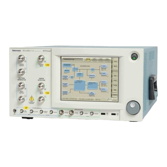
Product Description Product Description This Quick Start Guide supports the following Tektronix BERTScope Bit Error Ratio Analyzers/Pattern Generators: BSA85C Bit Error Ratio Analyzer, BSA85CPG Pattern Generator BSA125C Bit Error Ratio Analyzer, BSA125CPG Pattern Generator BSA175C Bit Error Ratio Analyzer, BSA175CPG Pattern Generator... -
Page 17: Features And Benefits
Product Description Features and Benefits Features Benefits Pattern Generation and Error Analysis Receiver BER compliance testing Integrated Stress Generator Stressed eye sensitivity (SRS) and jitter tolerance compliance testing Best BERT ease of use Engineer time and cost savings Rapid problem identification Integrated, BER-correlated eye diagram analysis BER contour analysis Fast understanding of signal integrity in terms of BER... -
Page 18: Documentation
Documentation Documentation In addition to this Quick Start Guide, the following documents are available: Online Help Programmer Online Guide Optional Applications Optional analysis capabilities available for BERTScope Analyzers: Error Correction Coding Emulation Software (included in STR) F/2 Jitter Generation at 8G (requires STR) J-MAP Jitter Decomposition Software JTOL... -
Page 19: Installation
Installation Installation Standard Accessories Keyboard Mouse Combined keyboard & mouse USB connector Power cord 3 cables Optional Accessories CR125ACBL High performance Delay Matched Cable Set (required for BERTScope Analyzer and Clock Recovery instrument in SSC applications) Operating Requirements Place the instrument on a cart or bench. The instrument should rest on its bottom or rear feet. An optional rack mounting kit is available. -
Page 20: Configuration
Configuration Configuration Hardware Connectors Front Panel In addition to the Clock and Data connectors on the front panel, several hardware connectors are provided. At the lower far left is a Chassis Ground connector, and far right, a USB port. Generator connectors are outlined in blue, and Detector connectors in green;... -
Page 21: Ensure Proper Precautions
Configuration Ensure proper precautions Ensure that proper precautions are observed against electrostatic discharge. Using suitable high quality coaxial cables with APC3.5 or SMA connectors, connect to the front panel interfaces as follows: Connect ‘Clock Output’ to ‘Clock Input’ ‘Data Output +’ to ‘Data Input +’ ‘Data Output –’... -
Page 22: Setting Up A Simple Ber Measurement
Setting Up a Simple BER Measurement Setting Up a Simple BER Measurement NOTES: The screen is touch-sensitive. Selections may be made by touching on screen icons, or by using a keyboard and mouse (if connected). Navigation between screens is easy – a shortcut to the Pattern Generator Screen and Error Detector Screen is available at any time at the bottom of the screen. -
Page 23: Troubleshooting Information
Setting Up a Simple BER Measurement Troubleshooting Information If the instrument does not behave as described here, some common areas to look for are: Does the Error Detector say “Unstable Clock”? Check that the Pattern Generator has its clock outputs switched on (press ‘Outputs On/Off’). Check that there is a good coax connection between the Generator Clock output (either + or –) and the Error Detector Clock Input. -
Page 24: References
References References Product Specifications PC Related: Display ..................TFT Touch Screen 640 x 480 VGA Touch Sensor................Analog Resistive ® Processor ................... Pentium 1.5 GHz or greater Hard Disk ..................40 GB or greater DRAM......................1 GB ® Operating System ............Windows XP Professional Remote Control Interfaces........ -
Page 25: Index
Pattern Generator ............8 Back-to-Back Setup..........7 Power Hardware Connectors..........6 Power On ..............6 Optional Connections..........7 Specification ............10 Contact Tektronix System Shutdown .............9 European Contact ............ iv Printer Setup..............9 USA Contact ............. i Customize Settings Remote Control PDF.............4 Change Amplitudes ..........8 Change Bit Rate ............ - Page 26 Index BSA85C, BSA125C, BSA260C Bit Error Ratio Analyzers Quick Start User Manual...
Need help?
Do you have a question about the BERTScope BSA85C and is the answer not in the manual?
Questions and answers