
Related Manuals for Magnetic MHTM FlowMotion


Summary of Contents for Magnetic MHTM FlowMotion
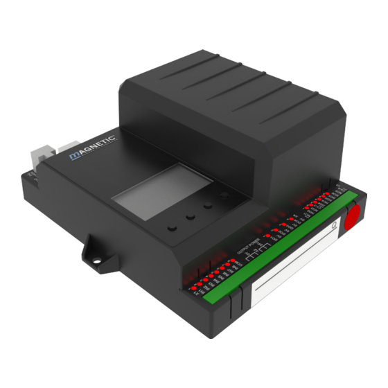
- Page 1 Description Swing door mSwing MHTM™ FlowMotion® Control unit MGC Doc.ID: 5817,0031EN Version 00...
- Page 2 Control unit MGC MAGNETIC AUTOCONTROL GMBH Grienmatt 20 D-79650 Schopfheim Germany Phone +49 7622 695 5 Fax +49 7622 695 802 info@magnetic-germany.com www.magnetic-access.com...
-
Page 3: Table Of Contents
Control unit MGC Contents Contents Notices on the document Purpose and contents of this description Symbols and illustrations used in this document 1.2.1 Warning notes and notes Target group 1.3.1 Personnel – activities and qualifications Digital inputs, digital outputs and relay outputs Digital inputs Digital outputs and relay outputs Illumination... - Page 4 Control unit MGC Contents Parameterisation directly at the control unit MGC Changing menu language Entering password Control unit elements Displays of the control unit Symbols in the display 5.5.1 Control button functions 5.5.2 Further symbols Setting display contrast Protecting parameterisation from access Parameterising value Switching the "Service"...
- Page 5 Control unit MGC Contents Function description Definition of "left" and "right" Start-up and regular movement sequence 7.2.1 Power-off state 7.2.2 Homing 7.2.3 Regular movement process 7.2.4 Permanent open Pulse operation in both directions with vend count Special cases within the motion sequence 7.4.1 Turning back during the closing movement 7.4.2...
- Page 6 Control unit MGC...
-
Page 7: Notices On The Document
Control unit MGC Notices on the document Notices on the document Purpose and contents of this description This document describes the control unit MGC from the programme versions listed below. Software number (software #) and software version (SW version) are displayed in the menu "Module info". -
Page 8: Symbols And Illustrations Used In This Document
Control unit MGC Notices on the document Symbols and illustrations used in this document 1.2.1 Warning notes and notes Warning notes are characterised by pictograms in these operating instructions. A warning note starts with a signal word that expresses the extent of the hazard. -
Page 9: Target Group
Target group 1.3.1 Personnel – activities and qualifications All work on the control unit may only be carried out by technicians and Magnetic MHTM™ FlowMotion® service experts with the following qualifications. Designation Qualification › Technician... -
Page 10: Digital Inputs, Digital Outputs And Relay Outputs
Control unit MGC Digital inputs, digital outputs and relay outputs Digital inputs, digital outputs and relay outputs WARNING Improper wiring and parameterisation of the control unit! Improper wiring and parameterisation of the control unit can lead to undesired functions and thus to injuries. ›... - Page 11 Control unit MGC Digital inputs, digital outputs and relay outputs Function Descriptions – Inputs that you assign this function "–" to are being deactivated. | Emergency open Emergency situation (Fail Safe) Connect fire brigade switches, emergency opening contacts, etc. to this input.
-
Page 12: Digital Outputs And Relay Outputs
Control unit MGC Digital inputs, digital outputs and relay outputs Digital outputs and relay outputs Definition of "Left" and "Right": ä Page 58, chapter 7.1. By parameterising the outputs, you assign certain functions to the outputs. For example, if you parameterise the "Buzzer/Siren (alarm)" function for output NO2, you must connect an acoustic signal transmitter to this output. - Page 13 Control unit MGC Digital inputs, digital outputs and relay outputs Function Description Passage clear Left Display for passage direction left free With a free passage to the left, a permanent signal is emitted via this output. You can also use this output to lock a pulse encoder, e.g. a card reader, for passage to the right if passage to the left is cleared.
-
Page 14: Illumination
Control unit MGC Digital inputs, digital outputs and relay outputs Function Description Locking (internal Connection of the locking via the brake booster use) The locking via the brake booster is connected to this output in the factory. Table 6: Function digital outputs and relay outputs Illumination You can order the swing door with the following optional illuminations: ›... -
Page 15: Parameterising Mswing
Control unit MGC Parameterising mSwing Parameterising mSwing The swing door is parameterised at the factory for applications with an opening angle of 2 x 90°. You have the following possibilities to parameterise the control unit MGC: › Directly at the control unit MGC ›... -
Page 16: Parameterisation Via The "Mswing Connect" Programme
Control unit MGC Parameterising mSwing Parameterisation via the "mSwing Connect" programme The programme "mSwing Connect" is available on the Magnetic website in the download center. You can also download the programme with the programme for the Service Module SM01 "SM-Downloader". - Page 17 Control unit MGC Parameterising mSwing Start the "mSwing Connect" programme on the laptop. √ The connection is established between the swing door and the "mSwing Connect" programme. If the connection is not established automatically, click the "Connect" button. √ The following view is displayed: Fig.
-
Page 18: Checking And Updating Software Version "Mswing Connect
Control unit MGC Parameterising mSwing 3.2.2 Checking and updating software version "mSwing Connect Prerequisite › Programme "mSwing Connect" is installed. › Laptop is connected to the Internet. Start the "mSwing Connect" programme on the laptop. Wait about 10 seconds. √ If an update is available, a respective message is displayed. -
Page 19: Updating Control Unit Mgc
Control unit MGC Parameterising mSwing 3.2.3 Updating control unit MGC Prerequisite › The latest firmware is installed on the Service Module SM01. › The latest software for mSwing is copied on the Service Module SM01. Start the "mSwing Connect" programme on the laptop. Open the "Service"... -
Page 20: Description "Mswing Connect" Programme
Control unit MGC Description "mSwing Connect" programme Description "mSwing Connect" programme Overview Fig. 5: Example "mSwing Connect" view Headline: Display of connection status and "Safety configuration" button Left side: Tabs and parameters Right side: Swing door mSwing status view... -
Page 21: Swing Door Mswing Status View
Control unit MGC Description "mSwing Connect" programme Swing door mSwing status view The status view shows the current position of the blocking element, signals certain events and shows the current status of the swing door. In the "Closed" position the value is 0°. When turning to the left, the value is negative. - Page 22 Control unit MGC Description "mSwing Connect" programme Fig. 7: Status view swing door mSwing, example status "WARNING" Locking active Status WARNING and warning message Confirm pending warning and update display Symbol Description No warning and no error is pending. WARNING A warning is pending.
-
Page 23: Passage Control" Tab
Control unit MGC Description "mSwing Connect" programme "Passage control" tab Use the "Passage control" tab to test the behaviour of the swing door. Fig. 8: "Passage control" tab The view offers the following options: Button / Description parameters Switch to the permanent open mode. Test input function "Open from left". -
Page 24: Settings" Tab
Control unit MGC Description "mSwing Connect" programme Button / Description parameters Hold-open time Display of the current hold-open time still available. If several opening pulses are present, the total hold-open time is not displayed. The hold-open time is counted down again from the set value with each opening pulse. - Page 25 Control unit MGC Description "mSwing Connect" programme Button / Description parameters Hold-open time ä Page 48, chapter 6.2.1. Permanent open ä Page 48, chapter 6.2.2. Speed ä Page 49, chapter 6.2.3. Security mode ä Page 50, chapter 6.2.4. Emergency ä Page 50, chapter 6.2.4. behaviour Buzzer/Siren ä...
-
Page 26: Service" Tab
Control unit MGC Description "mSwing Connect" programme "Service" tab Use the "Service" tab to select the target stop and set the 3 target positions "Closed (0°)", "Left" and " Right". The target stop is the stop that is approached during homing. The target stop should correspond to the "Open"... - Page 27 Control unit MGC Description "mSwing Connect" programme IMPORTANT! After each change of the mechanical end stops you must check the target positions and readjust them if necessary. Procedure Determine target stop if necessary. Set target position "Closed (0°)". The set position corresponds to 0°. Set target positions "Left"...
-
Page 28: Description Of The Buttons And Parameters
Control unit MGC Description "mSwing Connect" programme Click the "Closed (0°)" button. √ The motor is de-energised. The setting mode is indicated by flashing in yellow. Move the blocking element to the desired target position. √ After 5 seconds the target position "Closed (0°)" is accepted. The position corresponds to 0°. - Page 29 Control unit MGC Description "mSwing Connect" programme Button / Description parameters Expert – Perform reset. Reset MGC Read Event-Log Export and display event list. Date/Time Set the date and time. Information Display of serial number, software # and software versions Operating cycles Display of the current cycle counter reading of the swing door.
-
Page 30: Safety Settings" Tab
Control unit MGC Description "mSwing Connect" programme "Safety settings" tab WARNING Entering values that do not fit the blocking element! Entering values that do not fit the installed blocking element can lead to increased speed and incorrect torque, and thus to injuries. - Page 31 Control unit MGC Description "mSwing Connect" programme Entering safety parameters The values to be entered for the safety parameters can be found on a label that is attached to the blocking element. If you shorten the bracket, the values on the label are no longer valid.
- Page 32 Control unit MGC Description "mSwing Connect" programme Fig. 12: "Safety" tab, example input of wrong values, field "C" is red √ The written values are read back. The written values are displayed in a dialog box together with the check values. Fig.
-
Page 33: Safety Parameters For Shortened Blocking Elements "Bracket
Control unit MGC Description "mSwing Connect" programme 4.6.2 Safety parameters for shortened blocking elements "bracket" You can shorten the supplied blocking element "bracket" by sawing it off. In this case the safety parameters on the label are no longer valid. According to the blocking element length "L"... -
Page 34: Parameterisation Directly At The Control Unit Mgc
Control unit MGC Parameterisation directly at the control unit MGC Parameterisation directly at the control unit MGC Changing menu language The default setting in the MGC control unit is the menu language "English". Change the menu language as follows: The operational view is displayed. FlowMotion mSwing –... - Page 35 Control unit MGC Parameterisation directly at the control unit MGC The "Main menu" menu is displayed. The "Settings" menu has a dark background and is thus selected. Main menu Settings In-/Outputs Service System Fig. 16: "Main menu – Settings" view Select the "System"...
- Page 36 Control unit MGC Parameterisation directly at the control unit MGC Confirm selection with the right button « ». The following view is displayed. The menu language "English" is chosen. Language English French Spanish Fig. 19: "Language – English" view Select the language "German" with the two middle buttons « », «...
- Page 37 Control unit MGC Parameterisation directly at the control unit MGC Use the left button « » to leave the "Language" menu. The safety prompt "Save changes?" appears. Language Save changes? Fig. 22: "Safety prompt – Save changes?" view 10. Push the left button « »...
-
Page 38: Entering Password
Control unit MGC Parameterisation directly at the control unit MGC Entering password You need to enter a password in the following cases: › You would like to change parameters in the control unit and the password protection was activated. › You would like to reset the parameters to factory settings. -
Page 39: Control Unit Elements
Control unit MGC Parameterisation directly at the control unit MGC Use the right button « » to select the fourth digit of the password. The following view is displayed: Password Fig. 26: "Enter fourth digit of the password" view Use the two middle buttons « », «... -
Page 40: Displays Of The Control Unit
Control unit MGC Parameterisation directly at the control unit MGC Displays of the control unit mSwing FlowMotion – – – – Fig. 28: Example "Operational view" Type pedestrian gate, here mSwing Status display, here ready for operation Angle of rotation, here 0 Current function of the right control button, here accessing menu "Main menu"... - Page 41 Control unit MGC Parameterisation directly at the control unit MGC Hold-open time Fig. 29: Example "Screen Change Value" Parameter Current value Possible upper value Possible lower value Current functions of the control buttons...
-
Page 42: Symbols In The Display
Control unit MGC Parameterisation directly at the control unit MGC Symbols in the display 5.5.1 Control button functions The control unit is equipped with 4 control buttons. The function of the control buttons change depending on the current view in the display. The current functions are shown in the display. -
Page 43: Further Symbols
Control unit MGC Parameterisation directly at the control unit MGC 5.5.2 Further symbols Function Description Wrong password entered. Access denied. Reset values to factory settings. To do this, you must enter the password "0000". There is information. Check the "Information" menu. To do this, press the left operating button. -
Page 44: Setting Display Contrast
Control unit MGC Parameterisation directly at the control unit MGC Setting display contrast The display contrast of the control unit is adjustable after activation while the logo is still displayed. The logo is displayed for 3 seconds. If you push one of the middle buttons « », «... - Page 45 Control unit MGC Parameterisation directly at the control unit MGC 11. If the changes are to be saved, press the right button « ». The new hold- open time is activated. If the changes are not to be saved, press the left button « ».
-
Page 46: Switching The "Service" Mode On And Off
Control unit MGC Parameterisation directly at the control unit MGC Switching the "Service" mode on and off IMPORTANT! The service switch is located on the control unit. The control unit is only accessible when the blocking element, the hood and the outer tube have been removed. -
Page 47: Description Of Menus And Parameters
Control unit MGC Description of menus and parameters Description of menus and parameters "Information" menu Accessing and navigating The operational view is displayed. ä Page 40, Fig. 28. Press left button « ». Use the left button « » to scroll within the menu. The "Information"... -
Page 48: Settings" Menu
Control unit MGC Description of menus and parameters "Settings" menu 6.2.1 Hold-open time Operational view > Main menu > Settings > Hold-open time Parameter Description Hold-open time Set the hold-open time. The hold-open time is started by an opening pulse by a control device, such as a card reader. -
Page 49: Speed
Control unit MGC Description of menus and parameters 6.2.3 Speed Operating view > Main menu > Settings > Speed Parameter Description Close Select the speed of the closing movement for the blocking element. Options › Slow › Medium › Fast Factory setting ›... -
Page 50: Safety/Security
With the "High security" option, the swing door is permanently locked in the "closed" position. With an opening pulse the locking is released and then the movement is executed. As this setting is only intended for special cases, please consult Magnetic for this setting. Factory setting ›... -
Page 51: Signalling
Control unit MGC Description of menus and parameters 6.2.5 Signalling Operational view > Main menu > Settings > Signalling Parameter Description Buzzer/Siren Activate events for which an acoustic signal is to be triggered. Connect the acoustic signal to the "Buzzer/Siren (alarm)" output. An acoustic signal is possible for the following events: ›... -
Page 52: Service" Menu
Control unit MGC Description of menus and parameters "Service" menu This menu is only intended for Magnetic's service and only accessible with a password. 6.4.1 Gate HW Use the "Gate HW" menu to select the target stop and set the 3 target positions "Closed", "Left"... - Page 53 Control unit MGC Description of menus and parameters Operational view > Main menu > Service > Gate HW Parameter Description Target position right Check and adjust the angle of rotation of the blocking element. Observe the position of the mechanical end stops. If necessary, the mechanical end stops must be reset.
-
Page 54: Further Parameters
Control unit MGC Description of menus and parameters 6.4.2 Further parameters Operational view > Main menu > Service Parameter Description Cycles Display of complete passage procedures. Lifetime Display operating hours counter. The operating hours counter records the time, during which the pedestrian gate is supplied with electrical power. System time Displays the internal date and the internal clock. -
Page 55: Information" Menu
Control unit MGC Description of menus and parameters "Information" menu Operational view > Main menu > Information Parameter Description Serial No. Displays the serial number of the control unit Hardware Version Displays the present hardware version Software # Displays the present software number SW Version Displays the present software version Temperature... -
Page 56: Factory Settings" Menu
Control unit MGC Description of menus and parameters "Factory settings" menu IMPORTANT! The parameters of the control unit are stored in the three memory areas "Default settings", "Factory settings" and "User settings". The default settings are identical to the factory settings in these operating instructions. - Page 57 Control unit MGC Description of menus and parameters Press the right button « ». √ The safety prompt "Save changes?" appears. › If the changes are to be saved, press the right button « ». The current settings are reset to factory settings. A restart is performed. ›...
-
Page 58: Function Description
Control unit MGC Function description Function description Definition of "left" and "right" Fig. 31: Definition of "left" and "right" Left (function "Open from left" for a passage from left) Right (function "Open from right" for a passage from right) -
Page 59: Start-Up And Regular Movement Sequence
Control unit MGC Function description Start-up and regular movement sequence 7.2.1 Power-off state The motor is not energized in the power-off state. The locking is released. The blocking element can be moved freely. Ensure that the swing door can take up operation unhindered. The movement path of the blocking element must be free and limited by setting the mechanical end stops. -
Page 60: Pulse Operation In Both Directions With Vend Count
Control unit MGC Function description Pulse operation in both directions with vend count In pulse operation, a maximum of 3 opening pulses per side are accepted. If several opening pulses are received, the hold-open time is added up and counted down. If opening pulses are present in both directions, there is no motor movement or movement of the blocking element. -
Page 61: Emergency
Control unit MGC Function description 7.4.4 Emergency If the "Emergency situation" input is interrupted during operation, the swing door switches to the "Permanent open" operating mode. The behaviour of the blocking element depends on the setting of the "Emergency behaviour" parameter. -
Page 62: Corrective Action
Control unit MGC Corrective action Corrective action Safety in troubleshooting Qualification of personnel › Technician › Magnetic MHTM™ FlowMotion® service expert ä Page 9, chapter 1.3.1. Personal protective equipment Wear the following personal protective equipment: › Work clothes › Protective gloves ›... -
Page 63: Malfunctions Pedestrian Gate
Control unit MGC Corrective action Malfunctions pedestrian gate Malfunction: Display is difficult or impossible to read. Possible cause Corrective action Removal by Display contact set too light or Technician Correct display contact. ä Page dark. 44, chapter 5.6. Malfunction: The blocking element does not open. Possible cause Corrective action Removal by... -
Page 64: Event, Warning And Error Messages - Logic Control (Control Unit)
Control unit MGC Corrective action Error messages "ERROR" Faults that cannot be reset by the control unit are displayed as errors. The pedestrian gate is put out of service. If the function "Error" has been chosen for an output, this output is deactivated at pending errors (fail safe). - Page 65 Control unit MGC Corrective action Number Designation Possible cause Corrective action › 6103 FW default values After a software update Perform reset. recovered or after configuration of ä Page 71, chapter 8.4. WARNING › the gate type. If the error occurs repeatedly, replace the control unit MGC.
-
Page 66: Event, Warning And Error Messages - Motor Mhp2
Control unit MGC Corrective action Number Designation Possible cause Corrective action › 8130 Heartbeat error Communication to a Check whether all plugged plug-in module was in modules are listed in the WARNING interrupted. main menu. › Perform reset. ä Page 71, chapter 8.4. ›... - Page 67 Control unit MGC Corrective action Number Designation Possible cause Corrective action › 4210 Over temperature A high temperature was Check the motor detected. Motor temperature via the ERROR overloaded or blocked. "Motor MHP2" menu. The temperature must be below 100 °C. ›...
- Page 68 Control unit MGC Corrective action Number Designation Possible cause Corrective action › FFA1 Trajectory – Perform reset. ä Page 71, chapter 8.4. ERROR › Perform software update. › Check Motor. › FFA4 Vandalism An unauthorised Check locking. › passage was detected. Confirm warning via input.
-
Page 69: Event, Warning And Error Messages - Safety Controller
Control unit MGC Corrective action 8.3.3 Event, warning and error messages – Safety Controller Number Designation Possible cause Corrective action › 6150 Selftest failed EMC interference, Perform reset. motor control or ä Page 71, chapter 8.4. ERROR › microcontroller Perform software update. ›... -
Page 70: Event, Warning And Error Messages - All Modules
Control unit MGC Corrective action 8.3.4 Event, warning and error messages – All modules Number Designation Possible cause Corrective action › 5510 Controller selftest failed EMC interference, MGC Perform reset. control unit or ä Page 71, chapter 8.4. ERROR › microcontroller Perform software update. -
Page 71: Performing Reset
Control unit MGC Corrective action Performing reset If you use one of the following options, the control unit will perform a reset: › Switch of power supply and switch it on again after 10 s. › Press the two middle operating buttons on the control unit display for 5 s. ›... -
Page 72: Menu Structure
Control unit MGC Menu structure Menu structure Menu structure directly on the control unit MGC FlowMotion mSwing – – – – Errors, Warnings, Main menu Events Inputs Settings Outputs In-/Outputs Modul info Service System Information Motor MHP2 Safety Controller Factory settings Fig. - Page 73 Control unit MGC Menu structure Main menu Settings Hold-open time Permanent open In-/Outputs Speed Close Service Open Security mode Safety/Security System Emergency behaviour Information Signalling Buzzer/Siren Motor MHP2 Safety Controller Factory settings Fig. 33: "Settings" menu...
- Page 74 Control unit MGC Menu structure Main menu Settings In-/Outputs Inputs Digital inputs 1 – 8 Outputs Digital outputs 1 – 4 Relay outputs 1 – 6 Service Gate HW Align home position Align position left Target position left Align position right Target position right Homing direction Cycles...
-
Page 75: Index
Digital outputs ........10, 12 Logic voltage ..........55 Disconnect ..........17 Display contrast ........44 Display control unit ......... 40 Magnetic MHTM™ FlowMotion® service Symbols ..........42 expert ............9 Main menu password ......54 Malfunctions Emergency ..........61 All modules .......... - Page 76 Control unit MGC Index Menu Relay outputs........10, 12 Information .......... 47 Reset ............71 Settings ..........48 Restore factory settings ......56 Menu Setup ..........72 Right Mode “Service “ ........46 Definition ..........58 Module info ..........47 Motor temperature .........
- Page 77 Control unit MGC Index Warning ........... 12 Warning messages ......47, 63 Warning Notes Presentation .......... 8 X20-EN ............. 55...
- Page 78 Control unit MGC...
- Page 79 Control unit MGC...
- Page 80 MAGNETIC AUTOCONTROL GMBH Sales partner Grienmatt 20 D-79650 Schopfheim Germany Phone +49 7622 695 5 Fax +49 7622 695 802 info@magnetic-germany.com www.magnetic-access.com F10044448...
Need help?
Do you have a question about the MHTM FlowMotion and is the answer not in the manual?
Questions and answers