
Related Manuals for Magnetic MGCplus


Summary of Contents for Magnetic MGCplus
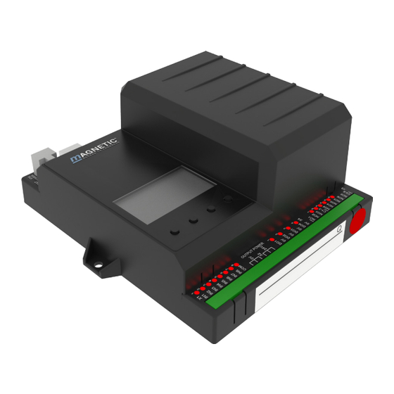
- Page 1 Description Pedestrian gate mWing MHTM™ FlowMotion® Control unit MGCplus Doc.ID: 5817,0033EN Version 00...
-
Page 2: In Direction
Control unit MGCplus MAGNETIC AUTOCONTROL GMBH Grienmatt 20 D-79650 Schopfheim Germany Phone +49 7622 695 5 Fax +49 7622 695 802 info@magnetic-germany.com www.magnetic-access.com... -
Page 3: Table Of Contents
Control unit MGCplus Contents Contents Notices on the document Purpose and contents of this description Symbols and illustrations used in this document 1.2.1 Warning notes and notes 1.2.2 Abbreviations used Target group 1.3.1 Personnel – activities and qualifications Definitions General Definitions... - Page 4 Control unit MGCplus Contents Protecting parameterisation from access Parameterise value Switching the "Service" mode on and off Description of menus and parameters Menu "Information" Menu "Settings" 6.2.1 Operating mode 6.2.2 Validations 6.2.3 Speed Wings 6.2.4 Safety 6.2.4.1 General 6.2.4.2 Low energy 6.2.4.3...
- Page 5 Control unit MGCplus Contents Corrective action Safety in troubleshooting Malfunctions pedestrian gate Event, warning and error messages in the display 7.3.1 Event, warning and error messages – Logic control (Control unit) Perform reset Menu setup Index...
- Page 6 Control unit MGCplus...
-
Page 7: Notices On The Document
Notices on the document Notices on the document Purpose and contents of this description This document describes the MGCplus control unit for the firmware versions listed below. The firmware number (Firmware #), the firmware name and the firmware ver- sion (FW Version) are displayed in the "Firmware" menu (System > Control unit >... -
Page 8: Symbols And Illustrations Used In This Document
Control unit MGCplus Notices on the document Symbols and illustrations used in this document 1.2.1 Warning notes and notes Warning notes are characterised by pictograms in these operating instructions. A warning note starts with a signal word that expresses the extent of the haz- ard. -
Page 9: Abbreviations Used
Control unit MGCplus Notices on the document Notes and recommendations IMPORTANT! The signal word IMPORTANT highlights useful notes and recom- mendations as well as information for an efficient and trou- ble-free operation. 1.2.2 Abbreviations used Abbreviation Description Contr. Controlled Open mode... -
Page 10: Target Group
Can assess the work assigned to her/him, recognises possible dangers and take suitable safety measures. › Magnetic MHTM™ FlowMotion® ser- Meets all requirements of the technician. › vice expert Trained and authorised by Magnetic. Table 3: Qualification of the personnel – MGCplus control unit... -
Page 11: Definitions
Control unit MGCplus Definitions Definitions General Definitions B1 B2 B3 B4 B5 B6 B7 B8 Side 1 Side 2 Paid Passage direction 1 Unpaid Slave (PE transmitter) Slave (PE transmitter) MGCplus Master (PE receiver) Master (PE receiver) Paid Passage direction 2... -
Page 12: Unauthorised Access Attempts
Control unit MGCplus Definitions Designation Description B1 to B14 Positioning of the light barriers (PE beams) 1 to 14. ä Page 11, Fig. 1. Side 1 The "Side 1" corresponds to the "Paid" zone or the zone controlled (protected area). -
Page 13: Operation Modes
Control unit MGCplus Operation modes Operation modes Description The pedestrian gate is equipped with various operating modes. You can force the various operating modes as follows: › Set the input with the corresponding function. For example, if you select the "Contr. D1/Closed D2" input, this operating mode is activated. - Page 14 Control unit MGCplus Operation modes Operating mode Description Closed D1/Free Closed direction 1 / Free direction 2 In direction 1 the pedestrian gate is closed. No validation is required for passages in direction 2. All persons can freely pass through the pedestrian gate in direction 2.
-
Page 15: Setting The Open Mode Via Control Unit
Control unit MGCplus Operation modes Setting the Open mode via control unit You have the following options to set the open mode for an operating mode: › Set the input with the corresponding function as in e.g. "Contr. D1/Closed D2 OM". -
Page 16: Special Operating Modes
Control unit MGCplus Operation modes Special operating modes Operating mode Description Boot-up The control unit boots up, initialises all hardware components and prepares to switch the drives on to perform homing. Wait for homing This operating mode is only relevant if the pedestrian gate is con- trolled via the API. -
Page 17: Control Of The Passages With "Control Direction 1" And/Or "Control Direction 2
Control unit MGCplus Operation modes Control of the passages with "Control direction 1" and/or "Control direction 2" 3.4.1 Explanations You have the option to control the behaviour of the pedestrian gate using the input functions "Control direction 1", "Control direction 2" and "Control open mode". - Page 18 Control unit MGCplus Operation modes Chapter 3.4.2 and 3.4.3 The chapters 3.4.2 and 3.4.3 show the resulting operating mode and the result- ing control unit behaviour depending on the input functions "Control direc- tion 1" and "Control direction 2". Please also note the parameter descriptions "Control variant"...
-
Page 19: Parameter "Control Variant" - Option "Variant 1
Control unit MGCplus Operation modes 3.4.2 Parameter "Control variant" – Option "Variant 1" This chapter describes the control unit behaviour if the option "Variant 1" was selected for the "Control variant" parameter. "Variant 1" is using the "Control direction 1", "Control direction 2" and "Control open mode"... - Page 20 Control unit MGCplus Operation modes Input "Con- Validation by Permanent Resulting operating mode trol direction changing signal at in- Resulting control unit behaviour ..." from not set put "Control to set at in- direction ..." put "Control direction ..." Contr. D1/Free D2 –...
-
Page 21: Parameter "Control Variant" - Option "Variant 2
Control unit MGCplus Operation modes 3.4.3 Parameter "Control variant" – Option "Variant 2" This chapter describes the control unit behaviour if the option "Variant 2" was selected for the "Control variant" parameter. "Variant 2" is using only the "Control direction 1" and "Control direction 2" and "Control open mode"... - Page 22 Control unit MGCplus Operation modes Input "Con- Validation by Permanent Resulting operating mode trol direction changing signal at in- Resulting control unit behaviour ..." from not set put "Control to set at in- direction ..." put "Control direction ..." Contr. D1/Free D2 OM –...
-
Page 23: Digital Inputs, Digital Outputs And Relay Outputs
Control unit MGCplus Digital inputs, digital outputs and relay outputs Digital inputs, digital outputs and relay outputs WARNING Improper wiring and parameterisation of the control unit! Improper wiring and parameterisation of the control unit can lead to undesired functions and thus to injuries. - Page 24 Control unit MGCplus Digital inputs, digital outputs and relay outputs Function Description – Inputs that you assign the function "–" to are being deactivated. Emergency open Emergency Connect fire service switches, emergency opening contacts, etc. to this in- put. As soon as this input is set, the control unit switches to emergency mode.
- Page 25 Control unit MGCplus Digital inputs, digital outputs and relay outputs Function Description Random check func- Activate random check function, confirm hits tion As soon as this input is set, the random check function is activated. ä Page 56, chapter 6.2.7, "Random check function" menu.
-
Page 26: Digital Outputs And Relay Outputs
Control unit MGCplus Digital inputs, digital outputs and relay outputs Digital outputs and relay outputs By parameterising the outputs, you assign certain functions to the outputs. For example, if you parameterise the "Buzzer (static)" function for output NO2, you must connect an acoustic signal transmitter to this output. - Page 27 Control unit MGCplus Digital inputs, digital outputs and relay outputs Function Description Buzzer To this output you connect a buzzer that does not generate its own beep pattern. The buzzer generates the beep pattern depending on the switching status of the output.
- Page 28 Control unit MGCplus Digital inputs, digital outputs and relay outputs Function Description Tailgating An unauthorised access attempt of the "Tailgating", type was detected in one direction. ä Page 12, chapter 2.2. Tailgating D1 Function such as "Tailgating" but only for direction 1.
-
Page 29: Parameterising Control Unit
Control unit MGCplus Parameterising control unit Parameterising control unit Changing menu language The default setting in the MGCplus control unit is the menu language "English". Change the menu language as follows: The operational view is displayed. FlowMotion mWing – –... - Page 30 Control unit MGCplus Parameterising control unit The "Main menu" menu is displayed. The "Settings" menu has a dark background and is thus selected. Main menu Settings In-/Outputs Information System Fig. 4: View "Main menu – Settings" Select the "System" menu with the two middle buttons «...
- Page 31 Control unit MGCplus Parameterising control unit Confirm selection with the right button « ». The following view is dis- played. The menu language "English" is chosen. Language English French Spanish Fig. 7: View "Language – English" Select the language "German" with the two middle buttons «...
- Page 32 Control unit MGCplus Parameterising control unit 10. Use the left button « » to leave the "Language" menu. The safety prompt "Save changes?" appears. Language Save changes? Fig. 10: View "Safety prompt – Save changes?" Push the left button «...
-
Page 33: Entering Password
Control unit MGCplus Parameterising control unit Entering password You need to enter a password in the following cases: › You would like to change parameters in the control unit and the password protection was activated. › You would like to reset the parameters to factory settings. -
Page 34: Control Unit Elements
» to enter the fourth digit of the password. Confirm the password with the right control button « ». Control unit elements Main menu Setup In-/Outputs Service System Mag01031 Fig. 15: MGCplus control unit elements Menu Current function of the 4 control buttons Control buttons... -
Page 35: Displays Of The Control Unit
Control unit MGCplus Parameterising control unit Displays of the control unit FlowMotion mWing – – – – 192.168.115.242 Fig. 16: Example "Operational view" Type pedestrian gate, here "mWing" Status display, here ready for operation Current function of the right control button, here calling menu "Main menu"... -
Page 36: Symbols In The Display
Control unit MGCplus Parameterising control unit Symbols in the display 5.5.1 Control button functions The control unit is equipped with 4 control buttons. The function of the control buttons change depending on the current view in the display. The current func- tions are shown in the display. -
Page 37: Further Symbols
Control unit MGCplus Parameterising control unit 5.5.2 Further symbols Clamp Description Wrong password entered. Access denied. The next validation is blocked by the random check function. There is information. Check the "Information" menu. To do this, press the left operating button. -
Page 38: Setting Display Contrast
Control unit MGCplus Parameterising control unit Setting display contrast The display contrast of the control unit is adjustable after activation while the logo is still displayed. The logo is displayed for 3 seconds. If you push one of the middle buttons «... -
Page 39: Switching The "Service" Mode On And Off
Control unit MGCplus Parameterising control unit Use the middle buttons « », « » to set the desired digit. Press the right button « ». 10. Use the left button « » to leave the "Hold-open Time" parameter. √ The safety prompt "Save changes?" appears. -
Page 40: Description Of Menus And Parameters
Control unit MGCplus Description of menus and parameters Description of menus and parameters Menu "Information" Call and navigate The operational view is displayed. ä Page 29, Fig. 2. Press left button « ». Use the left button « » to scroll within the menu. -
Page 41: Menu "Settings
Control unit MGCplus Description of menus and parameters Menu "Settings" 6.2.1 Operating mode Operational view > Main menu > Settings > Operating mode Parameter Description Control variant Select mode for the "Control direction 1", "Control direction 2" and "Control open mode" inputs. -
Page 42: Validations
Control unit MGCplus Description of menus and parameters Operational view > Main menu > Settings > Operating mode Parameter Description Emergency options Set the control unit behaviour during an emergency. If an input is set with the "Emergency open" function or if an input is no longer set with the "| Emergency open"... - Page 43 Control unit MGCplus Description of menus and parameters Operational view > Main menu > Settings > Validations Parameter Description Close delay – Set close delay. change The closing delay is the additional time that the wings remain open after a validated person has passed.
-
Page 44: Speed Wings
Control unit MGCplus Description of menus and parameters Operational view > Main menu > Settings > Validations Parameter Description Manual validation Function such as "Manual validation D1" but for direction 2. Table 19: Validations 6.2.3 Speed Wings Operational view > Main menu > Settings > Wing speed... -
Page 45: Safety
Control unit MGCplus Description of menus and parameters 6.2.4 Safety 6.2.4.1 General Operational view > Main menu > Settings > Safety > General Parameter Description Disable safety Enable and disable the test of the safety light barriers (safety PE beams). - Page 46 Control unit MGCplus Description of menus and parameters Operational view > Main menu > Settings > Safety > General Parameter Description Impact response Select the response for obstacle detection during the closing of the wings. Close IMPORTANT! The response for unauthorised access attempts is parameter- ised via the "Impact response Close"...
-
Page 47: Low Energy
Control unit MGCplus Description of menus and parameters 6.2.4.2 Low energy WARNING Entry of values that do not fit the blocking element! Entering values that do not fit the installed blocking element can lead to increased speed and incorrect torque, and thus to inju- ries. -
Page 48: Intrusion
Control unit MGCplus Description of menus and parameters Operational view > Main menu > Settings > Safety > Low energy Parameter Description New value S Adjust the value "S" to the installed blocking element. The adjustment re- quires a service password. -
Page 49: Wrong Direction
Control unit MGCplus Description of menus and parameters Operational view > Main menu > Settings > Safety > Intrusion Parameter Description Impact response Select the response for obstacle detection during the closing of the wings for Close the unauthorised access attempt of the "Intrusion" type. -
Page 50: Tailgating
Control unit MGCplus Description of menus and parameters Operational view > Main menu > Settings > Safety > Wrong direction Parameter Description Impact response Select the response for obstacle detection during the closing of the wings for Close the unauthorised access attempt of the "Wrong direction" type. -
Page 51: Safety
Control unit MGCplus Description of menus and parameters 6.2.5 Safety 6.2.5.1 Forced opening Operational view > Main menu > Settings > Safety > Forced opening Parameter Description React. forced open- Select response if the wings are attempted to be open from the closed posi- ing (Reaction forced tion by force. -
Page 52: Warning Light Barriers (Pe Beams)
Control unit MGCplus Description of menus and parameters 6.2.5.3 Warning light barriers (PE beams) Operational view > Main menu > Settings > Safety > Warning light barriers (PE beams) Parameter Description Warning light barri- Set the maximum time that a light barrier (PE beam) may be occupied. If one... -
Page 53: Ged No. 1 / Ged No. 2
Control unit MGCplus Description of menus and parameters 6.2.6.2 GED no. 1 / GED no. 2 The GEDs are parameterised using the "Mode", "Mode wrong direction" and "Validation response" parameters. For certain events such as "On tailgating" etc. you can choose between differ- ent display patterns. - Page 54 Control unit MGCplus Description of menus and parameters Operational view > Main menu > Settings > Signalling > GED no. 1 / GED no. 2 Parameter Description Validation response Select the GED behaviour when the set hold-open time is below a certain value.
- Page 55 Control unit MGCplus Description of menus and parameters Display pattern on the GED Option Description No special display pattern for this state. Dark GED switched off GED shows a red cross. Green GED shows a green arrow. Pulse red 1 Hz GED flashes in red with a frequency of 1 Hz.
-
Page 56: Random Check Function
6.2.7 Random check function The MGCplus control unit is equipped with the "Random check function" op- tion. This function allows random bag and identity control of persons. If a hit was generated by the random check function and the next validation is blocked by the random check function, the following symbol appears on the display of the control unit: «... - Page 57 Control unit MGCplus Description of menus and parameters Operational view > Main menu > Settings > Random check function Parameter Description Hit range The function depends on the selected mode. For the "Counting" mode, use this parameter to set the value at which a hit is to be generated.
-
Page 58: Home Offset
Control unit MGCplus Description of menus and parameters Operational view > Main menu > Settings > Random check function Parameter Description Direction Select the passage direction for which the random hits are to be generated. Options › Both: Random hits occur in both passage directions. With this option, vali- dations are not deleted. -
Page 59: Menu "Inputs/Outputs
Control unit MGCplus Description of menus and parameters Menu "Inputs/Outputs" 6.3.1 Digital inputs 1-8 ä Page 23, chapter 4.1. 6.3.2 Digital outputs 1-4 and relay outputs 1-6 ä Page 26, chapter 4.2. Menu "Information" 6.4.1 Operating mode Operational view > Main menu > Information > Operating mode... -
Page 60: Light Barriers (Pe Beams)
Control unit MGCplus Description of menus and parameters 6.4.2.2 In direction 2 Operational view > Main menu > Information > People counter > In direction 2 Parameter Description Passages total Shows the number of all validated and non-validated passages in direction 2. -
Page 61: Menu "System
› Internet access is available. › All IP settings are configured correctly. Via Magnetic, you can purchase additional hardware to connect the control unit to the Internet without connecting it to your LAN. Options › No remote support: The control unit does not send support information to Magnetic. -
Page 62: Restore Settings
Control unit MGCplus Description of menus and parameters 6.5.1 Restore settings IMPORTANT! The parameters of the control unit are stored in the three mem- ory areas "FW settings", "Factory settings" and "User settings". The FW settings are identical to the FW settings in these operat- ing instructions. - Page 63 Control unit MGCplus Description of menus and parameters Operational view > Main menu > Service Parameter Description Main menu Activate and deactivate password protection for the main menu password To activate a change of the settings, either call the operational view or switch the voltage supply on or off.
-
Page 64: Corrective Action
Control unit MGCplus Corrective action Corrective action Safety in troubleshooting Qualification of personnel › Technician › Magnetic MHTM™ FlowMotion® service expert Personal protective equipment Wear the following personal protective equipment: › Work clothes › Protective gloves › Safety shoes. WARNING Inappropriate troubleshooting! Inappropriate troubleshooting can cause severe injuries. -
Page 65: Malfunctions Pedestrian Gate
Control unit MGCplus Corrective action Malfunctions pedestrian gate Malfunction: Display is difficult or impossible to read. Possible cause Corrective action Removal by Display contact set too light or Technician Correct display contact. ä Page dark. 38, chapter 5.6. Malfunction: The blocking element does not open. -
Page 66: Event, Warning And Error Messages In The Display
Control unit MGCplus Corrective action Event, warning and error messages in the display The control unit differentiates between events, warnings and errors. The corre- sponding message is displayed. Event messages "INFO" Event messages inform about events. The pedestrian gate continues to operate normally. -
Page 67: Event, Warning And Error Messages - Logic Control
Control unit MGCplus Corrective action 7.3.1 Event, warning and error messages – Logic control (Control unit) "[nn]" is a placeholder for the number of the component that may be causing an error. Number Designation Possible cause Corrective action › ERROR... - Page 68 Control unit MGCplus Corrective action Number Designation Possible cause Corrective action › ERROR Error during initialisa- Input extension in slot Check slot number and tion of the IM16 input [nn] not mounted me- mounting of the IM16 in- 0x50nn1048 extension in the MGC chanically correct.
-
Page 69: Perform Reset
Control unit MGCplus Corrective action Perform reset If you use one of the following options, the control unit will perform a reset: › Switch of power supply and switch it on again after 10 s. › Press the two middle operating buttons on the control unit display for 5 s. -
Page 70: Menu Setup
Control unit MGCplus Menu setup Menu setup FlowMotion mWing – – – – 192.168.115.242 Error, Warning, Main menu Event messages Inputs Setup Outputs In-/Outputs Modul info Information System Service Fig. 18: Menu "Information" and "Main menu"... - Page 71 Control unit MGCplus Menu setup Main menu Settings Operating mode Control variant Delay permanent open Inputs/Outputs Emergency options Validations Hold-open time Information Close delay System Left direction 1 Left direction 2 Service Max. direction 1 Max. direction 2 Manual validation D1...
- Page 72 Control unit MGCplus Menu setup Settings Operating mode Validations Speed Wings Safety General Disable safety Impact response Open Impact delay Open Impact response Close Impact delay Close Low engery New value S New value T Security New value C Signalling...
- Page 73 Control unit MGCplus Menu setup Settings Operating mode Validations Speed Wings Safety Security Forced opening React. forced opening Delay forced opening Lock wings autom. Warning PE beams Signalling Buzzer GED no. 1 Mode Mode wrong direction Validation response Random check function...
- Page 74 Control unit MGCplus Menu setup Main menu Settings Inputs/Outputs Inputs Digital inputs 1 – 8 Outputs Digital outputs 1 – 4 Relay outputs 1 – 6 Information Operating mode People counter Light barriers (PE beams) Reboot System Language IP settings...
- Page 75 Control unit MGCplus Menu setup Information Operating mode Current mode Reason Target mode People counter In direction 1 Passages total Valid. passages Reverted Intrusion Wrong direction Tailgating In direction 2 Passages total Valid. passages Reverted Intrusion Wrong direction Tailgating Occupied...
- Page 76 Control unit MGCplus...
-
Page 77: Index
Control unit MGCplus Index Index Contr. D1/Free D2 Description .......... 14 Input function ........25 Symbole Contr. D1/Free D2 OM | Emergency open ........24 Input function ........25 | Error ............26 Control direction 1 Function ..........17 Input function ........24 Adopt new values ........ - Page 78 Control unit MGCplus Index Do not close Hit range ..........57 Intrusion ..........48 Hold-open time ........42 Tailgating ..........50 Home offset ..........58 Wrong direction ........49 Do not close if free ........49 Impact delay Close General ..........46 Emergency mode ........
- Page 79 Control unit MGCplus Index Manual validation D1 ......43 Passages total Manual validation D2 ......44 In direction 1 ........59 Max. direction 1 ........43 In direction 2 ........60 Max. direction 2 ........43 PE beams ........... 12, 60 Menu People counter ........
- Page 80 Control unit MGCplus Index System Wings closed ........... 26 Menu ........... 61 Wings locked ........... 26 Wings opened ......... 26 Wings opened D1 ........26 Tailgating ........... 12, 28 Wings opened D2 ........26 In direction 1 ........59 Wrong direction......... 12, 27 In direction 2 ........
- Page 81 Control unit MGCplus...
- Page 82 Control unit MGCplus...
- Page 83 Control unit MGCplus...
- Page 84 MAGNETIC AUTOCONTROL GMBH Sales partner Grienmatt 20 D-79650 Schopfheim Germany Phone +49 7622 695 5 Fax +49 7622 695 802 info@magnetic-germany.com www.magnetic-access.com F10044452...
Need help?
Do you have a question about the MGCplus and is the answer not in the manual?
Questions and answers