
Subscribe to Our Youtube Channel
Related Manuals for Magnetic MHTM FlowMotion


Summary of Contents for Magnetic MHTM FlowMotion
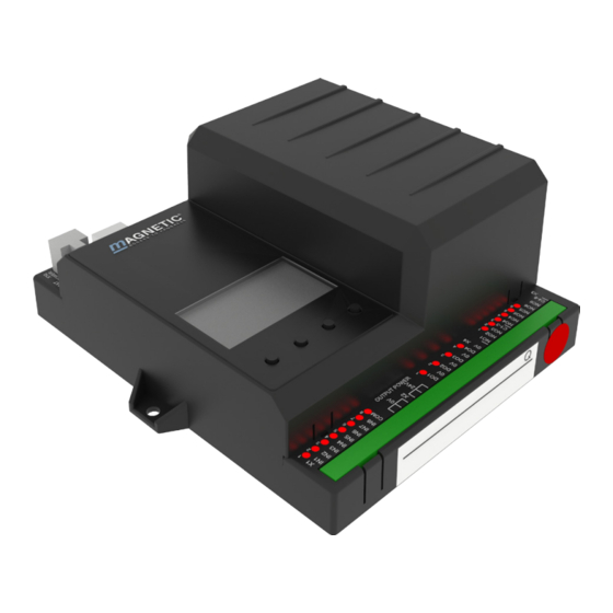
- Page 1 Description Turnstile mTripod MHTM™ FlowMotion® MGC control unit Doc. ID: 5817,0025EN Version 01...
- Page 2 MGC control unit MAGNETIC AUTOCONTROL GMBH Grienmatt 20 D-79650 Schopfheim Germany Phone +49 7622 695 5 Fax +49 7622 695 802 info@magnetic-germany.com www.magnetic-access.com...
-
Page 3: Table Of Contents
MGC control unit Contents Contents Notes on the document Purpose and contents of this description Symbols and illustrations used in this document 1.2.1 Warning notes and notes Target group 1.3.1 Personnel – activities and qualifications Digital inputs, digital outputs and relay outputs Digital inputs Digital outputs and relay outputs Digital power outputs of the MFM01 plug-in modules... - Page 4 MGC control unit Contents Menu "In-/Outputs" 4.3.1 Inputs 4.3.2 Outputs Menu "Service" 4.4.1 Gate HW 4.4.2 “Further parameters Menu "System" Menu "Passage counter" Menu "Information" Menu “Motor GW" (Gateway) Menu "Factory settings" Function description Definition of "left" and "right" Function sequence Start-up and regular movement sequence Operation modes 5.4.1...
- Page 5 MGC control unit Contents Menu setup Index...
- Page 6 MGC control unit...
-
Page 7: Notes On The Document
MGC control unit Notes on the document Notes on the document Purpose and contents of this description This document describes the MGC control unit from the program versions listed below. Software number (software #) and software version (SW version) are displayed in the menu "Module info". -
Page 8: Symbols And Illustrations Used In This Document
MGC control unit Notes on the document Symbols and illustrations used in this document 1.2.1 Warning notes and notes Warning notes are characterised by pictograms in these operating instructions. A warning note starts with a signal word that expresses the extent of the hazard. -
Page 9: Target Group
Target group 1.3.1 Personnel – activities and qualifications All work on the control unit may only be carried out by technicians and Magnetic MHTM™ FlowMotion® service experts with the following qualifications. Designation Qualification › Technician... -
Page 10: Digital Inputs, Digital Outputs And Relay Outputs
MGC control unit Digital inputs, digital outputs and relay outputs Digital inputs, digital outputs and relay outputs WARNING Improper wiring and parameterisation of the control unit! Improper wiring and parameterisation of the control unit can lead to undesired functions and thus to injuries. ›... - Page 11 MGC control unit Digital inputs, digital outputs and relay outputs Clamp Function – Inputs that you assign this function "–" to are being disabled. | Emergency open Emergency situation (Fail Safe) Connect fire service switches, emergency opening contacts, etc. to this input.
- Page 12 MGC control unit Digital inputs, digital outputs and relay outputs Clamp Function Lighting off Switching the lighting off and on As soon as +24 V DC are applied to this input, the floor lighting and the frame illumination are switched off. As soon as there is no signal at this input, the lighting is switched on.
-
Page 13: Digital Outputs And Relay Outputs
MGC control unit Digital inputs, digital outputs and relay outputs Digital outputs and relay outputs ä For the definition "Left" and "Right" see Page 43, chapter 5.1. By parameterising the outputs, you assign certain functions to the outputs. For example, if you parameterise the "Buzzer/Siren (alarm)" function for output NO2, you must connect an acoustic signal transmitter to this output. - Page 14 MGC control unit Digital inputs, digital outputs and relay outputs Function Function Passage free left Display for passage direction left free With a free passage to the left, a permanent signal is emitted via this output. You can also use this output to lock a pulse encoder, e.g. a card reader, for passage to the right if passage to the left is cleared.
-
Page 15: Digital Power Outputs Of The Mfm01 Plug-In Modules
MGC control unit Digital inputs, digital outputs and relay outputs Function Function GED green right Gate End Display connection Connect the GED green right to this output. Table 6: Function digital outputs and relay outputs Digital power outputs of the MFM01 plug-in modules You can equip the control unit with up to 4 optional MFM01 plug-in modules. - Page 16 MGC control unit Digital inputs, digital outputs and relay outputs Slot number Terminal plug- LED plug-in Function in module module Locking unit / drop arm Locking magnet left Green Locking magnet right Yellow Drop arm Passage right (frame illumination) / floor lighting Passage blocked right Green Passage free right...
-
Page 17: Parameterising Control Unit
MGC control unit Parameterising control unit Parameterising control unit Changing menu language The default setting in the MGC control unit is the menu language "English". Change the menu language as follows: The operational view is displayed. FlowMotion mTripod-M – – –... - Page 18 MGC control unit Parameterising control unit The "Main menu" menu is displayed. The "Setup" menu has a dark background and is thus selected. Main menu Setup In-/Outputs Service System Fig. 4: View "Main menu – Setup" Select the menu "System" with the two middle buttons " ", "...
- Page 19 MGC control unit Parameterising control unit Confirm selection with the right button " ". The following view is displayed. The menu language "English" is chosen. Language English French Spanish Fig. 7: View "Language – English" Select the language "German" with the two middle buttons " ", "...
- Page 20 MGC control unit Parameterising control unit Use the left button " " to leave the "Language" menu. The safety prompt "Save changes?" appears. Language Save changes? Fig. 10: View "Safety prompt – Save changes?" Push the left button " " if you do not want to save the changes. The menu language "English"...
-
Page 21: Entering Password
MGC control unit Parameterising control unit Entering password You need to enter a password in the following cases: › You would like to change parameters in the control unit and the password protection was activated. › You would like to reset the parameters to factory settings. If a password is required, the following view is displayed: Password –... -
Page 22: Control Unit Elements
MGC control unit Parameterising control unit Use the right button " " to select the fourth digit of the password. The following view is displayed: Password Fig. 14: View "Enter fourth digit of the password" Use the two middle buttons " ", "... -
Page 23: Displays Of The Control Unit
MGC control unit Parameterising control unit Displays of the control unit FlowMotion mTripod-M – – – – Fig. 16: Example "Operational view" Type pedestrian gate here mTripod electromotive Status display, here ready for operation Angle of rotation, here 0 Current function of the right control button, here calling menu "Main menu" Validations right, here locked Hold-open time right, here locked Operating display, here passage direction left enabled... -
Page 24: Symbols In The Display
MGC control unit Parameterising control unit Symbols in the display 3.5.1 Control button functions The control unit is equipped with 4 control buttons. The function of the control buttons change depending on the current view in the display. The current functions are shown in the display. -
Page 25: Further Symbols
MGC control unit Parameterising control unit 3.5.2 Further symbols Clamp Description Wrong password entered. Access denied. Reset values to factory settings. To do this, you must enter the password "0000". The next validation is blocked by the random function. There is information. Check the "Information" menu. To do this, press the left operating button. -
Page 26: Setting Display Contrast
MGC control unit Parameterising control unit Setting display contrast The display contrast of the control unit is adjustable after activation while the logo is still displayed. The logo is displayed for 3 seconds. If you push one of the middle buttons " ”, "... - Page 27 MGC control unit Parameterising control unit 11. If the changes are to be saved, press the right button " ". The new hold- open time is activated. If the changes are not to be saved, press the left button " ".
-
Page 28: Switching The "Service" Mode On And Off
MGC control unit Parameterising control unit Switching the "Service" mode on and off In service mode, all opening signals are ignored. Switch on mode "Service" Switch the "Service" switch for the "Service" mode. The LED lights red. The display backlighting flashes. Switch off mode "Service"... -
Page 29: Description Of Menus And Parameters
MGC control unit Description of menus and parameters Description of menus and parameters Menu "Information" Call and navigate The operational view is displayed. ä Page 23, Fig. 16. Press left button " ". Use the left button " " to scroll within the menu. The "Information"... -
Page 30: Menu "Setup
MGC control unit Description of menus and parameters Menu "Setup" 4.2.1 Hold-open time Operational view > Main menu > Setup > Hold-open time Parameter Description Hold-open time Set the hold-open time. The hold-open time is started by an opening impulse by a control device, such as a card reader. -
Page 31: Interlock
MGC control unit Description of menus and parameters 4.2.3 Interlock Operational view > Main menu > Setup > Interlock Parameter Description Interlock Activate and deactivate the "Interlock" function. If the interlock has been activated, further rotation of the blocking element is blocked for 1 second after each pass. -
Page 32: Vend Count
MGC control unit Description of menus and parameters 4.2.5 Vend count Operational view > Main menu > Setup > Vend count Parameter Description Counter left Displays the current counter for validations in the "Left" direction. Counter right Displays the current counter for validations in the "Right" direction. Max. -
Page 33: Signalling
MGC control unit Description of menus and parameters 4.2.6 Signalling Operational view > Main menu > Setup > Signalling Parameter Description Buzzer/Siren Activate events for which an acoustic signal is to be triggered. Connect the acoustic signal to the "Buzzer/Siren (alarm)" output. An acoustic signal is possible for the following events: ›... - Page 34 MGC control unit Description of menus and parameters Operational view > Main menu > Setup > Signalling Parameter Description GED mode left Set the behaviour of the optional GEDs. Options › Off: The display is dark. › Red: The display is permanently red. ›...
-
Page 35: Random Function
MGC control unit Description of menus and parameters 4.2.7 Random function The MGC control unit is equipped with the "random function" option. This function allows random bag and identity control of persons. If a hit was generated by the random function and the next validation is blocked by the random function, the following symbol appears on the display of the control unit: "... - Page 36 MGC control unit Description of menus and parameters Operational view > Main menu > Setup > Random function Parameter Description Hit range The function depends on the selected mode. For the "Counting" mode, use this parameter to set the value at which a hit is to be generated.
-
Page 37: Menu "In-/Outputs
MGC control unit Description of menus and parameters Operational view > Main menu > Setup > Random function Parameter Description Direction Select the passage direction for which the random hits are to be generated. Options › Both: Random hits occur in both passage directions. With this option, validations are not deleted. -
Page 38: Menu "Service
MGC control unit Description of menus and parameters Menu "Service" 4.4.1 Gate HW Operational view > Main menu > Setup > Gate HW Parameter Description Homing offset Mechanical tolerances can result in the blocking arm not being exactly in the middle position after homing. -
Page 39: Further Parameters
MGC control unit Description of menus and parameters 4.4.2 “Further parameters Operating view > Main menu > Service Parameter Description Cycles Display of complete passage procedures. Lifetime Display operating hours counter. The operating hours counter records the time, during which the pedestrian gate is supplied with electrical power. System time Displays the internal date and the internal clock. -
Page 40: Menu "Passage Counter
MGC control unit Description of menus and parameters Menu "Passage counter" Operational view > Main menu > Passage counter Parameter Description From left Display of the number of passages completed from the left. If necessary, the value can be changed. Setting range ›... -
Page 41: Menu "Motor Gw" (Gateway)
MGC control unit Description of menus and parameters Menu “Motor GW" (Gateway) Operational view > Main menu > Motor GW Parameter Description Motor temperature Display of the current motor temperature. Motor-SW Display of the present motor software. Information Displays information on the module "Motor GW". Serial number (serial no.), hardware version, software # and software version of the module "Motor GW"... - Page 42 MGC control unit Description of menus and parameters If you would like to assume the default settings as operating settings and the factory settings were overwritten first, you need to use the option "Default settings as factory settings" and then the option "Restore factory settings". Option "Restore factory settings"...
-
Page 43: Function Description
MGC control unit Function description › If the changes are to be saved, press the right button . The current settings are reset to factory settings. A restart is performed. › If the changes are not to be saved, press the left button Press the left button repeatedly until the operational view is displayed again. -
Page 44: Function Sequence
MGC control unit Function description Function sequence Start The control unit receives an opening impulse. Depending on the configuration of the inputs, only one direction can be released. The free and Passage is possible. the blocked directions can be signalled via optional displays. -
Page 45: Start-Up And Regular Movement Sequence
MGC control unit Function description Start-up and regular movement sequence Power-off state The motor is not energized in the power-off state. The lock is released and the capstan with the three blocking arms can be turned freely. For turnstiles with "Drop arm"... -
Page 46: Operation Modes
MGC control unit Function description Operation modes 5.4.1 Impulse operation in both directions without vend count The two inputs "Open from left" and "Open from right" are used to clear passage in the corresponding direction for one passage each. The impulse must be present between 0.2 and 1 sec. -
Page 47: Permanent Open In Both Directions
MGC control unit Function description The processing of the stored pulses is independent of the sequence in which the pulses were received. This means that if there are pulses for both passage directions, passage in both directions is possible. When a passage has been completed, the control unit verifies again for which directions pulses are still stored. -
Page 48: Special Cases Within The Motion Sequence
MGC control unit Function description Special cases within the motion sequence Stopping in mid-movement If the blocking element is stopped in mid-movement, e.g. from the user not moving on, the motor will continue to move at low torque. Turning back during the movement If an attempt is made to turn back the blocking element during the passage, the reaction depends on the angle of rotation. -
Page 49: Troubleshooting
MGC control unit Troubleshooting Troubleshooting Safety in troubleshooting Qualification of personnel › Technician › Magnetic MHTM™ FlowMotion® service expert ä See Page 9, chapter 1.3.1. Personal protective equipment Wear the following personal protective equipment: › Work clothes › Protective gloves ›... -
Page 50: Malfunctions Turnstile
MGC control unit Troubleshooting Malfunctions turnstile Malfunction: Display is difficult or impossible to read. Possible cause Corrective action Removal by Display contact set too light or Technician Correct display contact. ä Page dark. 26, chapter 3.6. Malfunction: Blocking element does not rotate. Possible cause Corrective action Removal by... -
Page 51: Event, Warning And Error Messages - Logic Control (Control Unit)
MGC control unit Troubleshooting Error messages "ERROR" Faults that cannot be reset by the control unit are displayed as errors. The pedestrian gate is put out of service. If the function "Error" has been chosen for an output, this output is deactivated at pending errors (fail safe). - Page 52 MGC control unit Troubleshooting Number Designation Possible cause Corrective action › 6105 Error on homing The pedestrian gate Check motor could not execute a communication. ERROR › homing. Check mechanics. › Check the homing sensor › Perform reset ä Page 55, chapter 6.4.
-
Page 53: Event, Warning And Error Messages - Motor Gw
MGC control unit Troubleshooting 6.3.2 Event, Warning and Error messages – Motor GW Number Designation Possible cause Corrective action › 2220 Over current Overcurrent was If no impact has occurred, detected check the wiring. WARNING › If required, contact Warning may occur in Service. -
Page 54: Event, Warning And Error Messages - All Modules
MGC control unit Troubleshooting Number Designation Possible cause Corrective action FF3A Motor update This message is for – performed information only. INFO Table 25: Event, Warning and Error messages – Motor GW 6.3.3 Event, Warning and Error messages – all Modules Number Designation Possible cause... -
Page 55: Perform Reset
MGC control unit Troubleshooting Perform reset Control unit reset is performed as follows: › Switch of power supply and switch it on again after 10 seconds. › Press the two middle control buttons on the display of the control unit for 5 seconds. - Page 56 MGC control unit Menu setup Menu setup FlowMotion mTripod-M – – – – Error, Warning, Main menu Event messages Inputs Setup Outputs In-/Outputs Modul info Service System Passage counter Information Motor GW Factory reset Fig. 20: Menu "Information" and "Main menu"...
- Page 57 MGC control unit Menu setup Main menu Setup Hold-open time Permanent open In-/Outputs Interlock Service Safety/Security Safety mode Holding force System Vend count Counter left Passage counter Counter right Max. impulse count Information Max. imp. w/o passage Motor GW Signalling Buzzer/Siren Signal move Factory reset...
- Page 58 MGC control unit Menu setup Main menu Setup In-/Outputs Inputs Digital inputs 1 – 8 Outputs Digital outputs 1 – 4 Relay outputs 1 – 6 Service Gate HW Homing offset Align home position Drop arm Cycle Lifetime System time Main menu password System Language...
- Page 59 MGC control unit Index Index Error ............13 Error messages ........29, 51 Event messages ......... 29, 50 Symbole | Emergency open ........11 | End switch drop arm ......12 Factory settings ........41 | Error ............13 From left ..........40 | Over-climb detection ......
- Page 60 Permanent open ........30 Logic voltage ..........40 Both directions ........47 Plug-in module MFM01 ......15 Functions ..........16 Magnetic MHTM™ FlowMotion® service Power-off state ........45 expert ............9 PSU-FB ............. 40 Main menu password ......39 Malfunctions All modules ..........
- Page 61 MGC control unit Index Under-crawl detection......11 User settings as factory settings ....41 Vandalism ..........14 Vandalism attempt ........48 Vend count ..........32 Warning ........... 13 Warning messages ......29, 50 Warning Notes Presentation .......... 8 X20-EN ............. 40...
- Page 62 MGC control unit...
- Page 63 MGC control unit...
- Page 64 MAGNETIC AUTOCONTROL GMBH Sales partner Grienmatt 20 D-79650 Schopfheim Germany Phone +49 7622 695 5 Fax +49 7622 695 802 info@magnetic-germany.com www.magnetic-access.com F10044415...
Need help?
Do you have a question about the MHTM FlowMotion and is the answer not in the manual?
Questions and answers