Advertisement
Quick Links
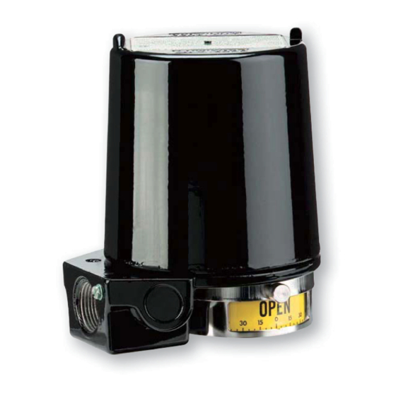
The
Proximity
Controls
Indicator/Transmitter is a line of position indicators
with a selection of various output options. Three model
styles make up the Mark Series to cover almost any
application. A magnetic drive that completely seals the
switch compartment from the atmosphere for maximum
leak protection is utilized in the Mark 1. The Mark 3 uses
the same magnetic drive of the Mark 1, but it can be used
for multi-turn applications with 1 to 25 revolutions, such
as gate valves. A through shaft drive is incorporated in
the Mark 4 making the unit a lower cost alternative to the
Mark 1 for applications that are not as demanding.
Standard models in the Mark Series have visual position
submersible. A large variety of outputs are available to
outputs of 13 varieties including inductive sensors,
high temperature switches, gold contact switches,
hermetically sealed switches, and high current switches.
Aside from switch outputs, the Mark Series offers
potentiometer outputs, 4-20 mA transmitters, and HART
communication.
The units are purchased for either direct drive
applications, such as rotary valves, or lever drive
applications, such as linear valves. For the Mark 1, 3,
and 4 this instruction manual starts with installation of
the unit to the device being monitored, and the set up
of switch models. Separate instructions follow covering
the potentiometer and transmitter set up if your unit has
those options.
This product uses FreeRTOS (www.FreeRTOS.org)
version 8.0.1. A copy of the original FreeRTOS source
shall be provided upon request.
Series Mark Position Indicator/Transmitter
Series
Mark
Position
®
Introduction. . . . . . . . . . . . . . . . . . . . . . 1
Dimensions . . . . . . . . . . . . . . . . . . . . . 2
. . . . . . . . . . . . . . . . . . . 2-3
Junction Package . . . . . . . . . . . . . . . . . .
Factory Sealed Leads . . . . . . . . . . . . . . . .
Mounting Kits for Valves . . . . . . . . . . . . . . .
Mark 1 and 4 Direct Drive Installation . . . . . . . . 7
Mark 1 and 4 Lever Drive Installation . . . . . . . . 8
Mark 3 Direct and Lever Drive Installation . . . . . . 9
Mark 1, 3, and 4 with Potentiometer Installation . . 10
Mark 1, 3, and 4 with Transmitter Installation . . 11-12
Mark 1, 3, and 4 Transmitter with
HART
Communication Protocol . . . . . . . . . 12-13
®
Wiring, Intrinsic Safety and Warnings . . . . . . 14-15
Schematics: General and Intrinsic Safety . . . .
Maintenance . . . . . . . . . . . . . . . . . . . . 20
1
. . . . . . . . . . . . 4-5
Advertisement

Related Manuals for Dwyer Instruments PROXIMITY Series


Summary of Contents for Dwyer Instruments PROXIMITY Series
- Page 1 Series Mark Position Indicator/Transmitter Proximity Controls Introduction..... . 1 Series Mark Position Indicator/Transmitter is a line of position indicators Dimensions ..... 2 with a selection of various output options.
- Page 2 CLEARANCE REQUIRED LEVER 1-1/16 FOR COVER REMOVAL DRIVE [26.99] 4-1/4 [107.95] 2-3/8 5/16 [7.94] [60.33] 3 [76.20] .249 ± .001 DIRECT [6.32 ± .03] DRIVE *4-9/16 [115.89] 5-15/16 [150.81] 1-1/4 [31.75] 1-9/16 [39.69] 4-7/8 [123.83] 2-3/8 1 [25.40] #6-32 UNC [6.35] [60.33] THREAD...
- Page 3 Switch Type: See model chart on pages 4 and 5. See model chart on pages 4 and 5. ± 0.5% of FS. Optional ± 0.25% of FS. 1.5 watt maximum. ± 0.5% of FS. Optional ± 0.25% of FS. 5-30 VDC. 50 mA.
- Page 4 Construction Mark 1, magnetic coupling Available Mark 3, multi-turn Options “A” Mark 4, thru-shaft available with corresponding construction style Mark Output Type 1 switch 2 switches 4 switches approved units only) AS-interface and 1 switch; Available with switch types B, I, R, W AS-interface and 2 switches;...
- Page 5 Available Options “A” available with corresponding construction style Mark A direct or yoke drive without visual indicator Direct drive (or yoke) with visual indicator Method Direct or yoke drive with visual indicator, single window Aluminum, painted black Aluminum, painted white epoxy with SS trim Aluminum, painted red 7 thru 20 Long dwell cam (not on Mark 3)
-
Page 6: Visual Indicator
Complete factory assembled packages combine visual Mounting kits are available for direct installation of the indication, solenoids, switches and transmitter in a single Proximity Controls Mark Series onto most valve and actuator brands. Proximity Controls has over 2000 kits assembly which saves labor and reduces cost. The available and can custom make kits for any application. - Page 7 A. Using a wrench or power, rotate the actuator shaft to extreme clockwise position. All switches should change to their opposite function. B. The cam can be relocated and repositioned by grasp cam on knurled segment of cam surface. Simply rotate the cam on spline attached to the pressure on cam when it is at proper actuation point.
- Page 8 A. Operate actuator to full closed position. Set screws hold cams in place on the shaft. For manual cams, grasp cam on knurled segment of cam surface and simply rotate cam to get correct actuation point. Clicks on cam in direction of protruding actuation segment of cam surface, and rotating, eliminates incremental on cam when at proper actuation point.
-
Page 9: Shaft Drive
5. The following chart shows the various combinations of screw positions and resulting revolutions between switch actuation. CAM SCREWS Between Switch Switch #1 Switch #2 YOKE DRIVE CLOCKWISE revolutions or partial revolutions can be selected by turning the cam screws in or out when located at the nearest location shown above. - Page 10 TERMINAL 3 TERMINAL 2 TERMINAL 1 Resistance Between Pins Potentiometer 1000 2000 1000 1000 1529 5000 14.7 2500 1178 2500 3823 10000 29.4 5000 2354 5000 20000 58.8 10000 4708 10000 15294 1. Attach the switch to the actuator or valve. Refer to p.
- Page 11 1 2 3 CLOCKWISE ROTATION Potentiometer 1000 1.5 turns 8.5 turns 2000 .75 turns 4.3 turns Models 15XXX, 35XXX and 45XXX Rotary Position Indicating Switches contain a 4-20 mA transmitter and two Single Pole Double Throw (SPDT) switches. Models 150XX, 350XX and 450XX contain a 4-20 mA transmitter only, no switches.
- Page 12 ® A. Set the valve at the position where you want the meter to read 0% (that is 4 mA). It may be necessary to move the plug connector to change the direction of current output to increasing for clockwise rotation or vice versa.
-
Page 13: Test Point
WP SHUNT FAULT SHUNT • Two test points are provided as a convenience for FIND SHUNT HART ® attaching HART ® communication master. COMMUNICATION SQUAWK MASTER* 4-20 mA METER 24 VDC from communications with a HART communication ® POWER SUPPLY **250Q changes. - Page 14 • Complete all electrical wiring in accordance with local • It may be necessary to segregate power and signal NAMUR Sensor must be treated as separate intrinsically circuits in separate conduit entries. safe circuits. • For units supplied with both internal ground and external bonding terminals, the ground screw inside the housing must be used to ground the control.
- Page 15 électriques sous tension. • Repairs only to be conducted by Dwyer Instruments, hors tension. Inc. • Ne pas ouvrir le ni une unité avec interface AS en Instruments, Inc.
- Page 16 1. Units supplied with switch option A, G, H, M or T have screw terminals on the back side of the switch for terminating wires. 2. UL and CSA units supplied with switch option D are 3. Units supplied with switch option B, C, I, R, S, V or 2 or 4 termination points.
- Page 17 INTRINSICALLY SAFE BARRIERS INTRINSICALLY SAFE BARRIERS SW 4 SW 2 ABOVE 1ST SWITCH SWITCH SW 3 SW 1 ABOVE 2ND BOTTOM SWITCH SWITCH SWITCH 2 SWITCH 4 ABOVE 1ST SWITCH TOP SWITCH SWITCH 3 SWITCH 1 ABOVE 2ND SWITCH BOTTOM SWITCH SW 4 SW 2 ABOVE 1ST...
- Page 18 USE CONNECTOR SUPPLIED POTENTIOMETER WITH SWITCH ONLY. MAKE SURE CONNECTOR IS PUSHED ON ALL THE WAY TO ASSURE A TIGHT CONNECTION. TRANSMITTER SW 6 SW 4 SW 2 ABOVE 5TH ABOVE 1ST ABOVE 3RD SWITCH SWITCH SWITCH SW 5 SW 1 SW 3 ABOVE 4TH ABOVE 2ND...
- Page 19 TERMINAL 3 SEE WIRING SCHEMATIC SPAN ADJUSTMENT TERMINAL 2 SEE WIRING SCHEMATIC POTENTIOMETER BYPASS TERMINAL 1 SEE WIRING SCHEMATIC BY OTHERS WIRING SCHEMATIC TERMINAL 2 SEE WIRING WIRING SCHEMATIC SCHEMATIC 12 VDC TERMINAL 1 SEE WIRING 24 VDC SCHEMATIC BY OTHERS SEE WIRING WIRING SCHEMATIC SCHEMATIC...
- Page 20 This warranty does not apply if the maximum ratings label is removed or if the instrument or equipment is abused, altered, used at ratings above the HART is a registered trademark of Hart Communication Foundation ® ©Copyright 2021 Dwyer Instruments, Inc.
Need help?
Do you have a question about the PROXIMITY Series and is the answer not in the manual?
Questions and answers
Kindly send your best offer for Limit Switch, P/N 49885, Supplier: CCI, Used for: Severe Service Valves (Mfr. Proximity Controls, P/N 44RD1J2MTB 24VDC M20 IP 67 SPDT