Table of Contents
Advertisement
Quick Links
Instruction Manual
®
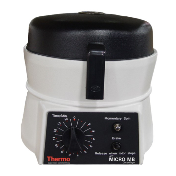
IEC Micro MB
Centrifuges
Cat. No.3413: 120 VAC, 50/60Hz (no rotor)
Cat. No.3414: 240 VAC, 50/60Hz (no rotor)
Cat. No.3415: 120 VAC, 50/60Hz (837 rotor)
Cat. No.3416: 240 VAC, 50/60Hz (837 rotor)
Cat. No.3411: 120 VAC, 50/60Hz (275 rotor)
Cat. No.3426: 240 VAC, 50/60Hz (275 rotor)
IM3411 Rev. 4
11 January 2004
Analyze Detect Measure Control ™
Advertisement
Table of Contents

Subscribe to Our Youtube Channel
Related Manuals for Thermo 3413


Summary of Contents for Thermo 3413
- Page 1 Instruction Manual ® IEC Micro MB Centrifuges Cat. No.3413: 120 VAC, 50/60Hz (no rotor) Cat. No.3414: 240 VAC, 50/60Hz (no rotor) Cat. No.3415: 120 VAC, 50/60Hz (837 rotor) Cat. No.3416: 240 VAC, 50/60Hz (837 rotor) Cat. No.3411: 120 VAC, 50/60Hz (275 rotor) Cat.
-
Page 3: Table Of Contents
Contents 1. Introduction ............3 1.1 Product Description ............4 1.2 Hematocrit Test (using 275 rotor) ......... 4 2. Installation............4 2.1 Receive the Unit ............4 2.2 Prepare the installation site .......... 4 2.3 Verify Power Configuration ........... 5 2.4 Moving the Unit............. -
Page 4: Introduction
There are six models: 3. Complete and return the postage-paid warranty card. • Cat. No. 3413 for 120 V, 50/60 Hz (No Rotor) 2.2 Prepare the installation site • Cat. No. 3414 for 240 V, 50/60 Hz (No Rotor) The unit normally resides on a bench top. -
Page 5: Verify Power Configuration
2.3 Verify Power Configuration 3. Operation 1. Verify that the correct power cord and connector is provided for your installation. WARNING WARNING Do not open the cover before the rotor comes to a The unit requires a grounded power supply (3-outlet). complete stop. -
Page 6: Starting And Stopping A Run
4. Once the rotor has come to a complete stop, unlatch and lift the cover. 3.3 Rotor Removal To remove the rotor, use the spanner wrench (Thermo Electron Part No. 1883) to loosen the locking nut(s) and lift the rotor off of the motor shaft. -
Page 7: Maintenance
4.4 Storage: Keep the Unit Dry 4. Maintenance Store parts on a soft surface to avoid damage. Rotors and other parts should be clean and dry. Store them 4.1 Care and Cleaning open to the air, not in a plastic bag, so any residual •... -
Page 8: Specifications
5. Specifications 6. Drawings/Parts 11,600 RPM minimum Rotation Speed 14,000 RPM maximum 13,200 xg (275 rotor) minimum Item Description 120V 240V Relative Centrifugal 8,700 xg (837 rotor) minimum 19,200 xg (275 rotor) maximum Force Base 49780 12,700 xg (837 rotor) maximum Brake Resistor 41313 Acceleration... - Page 9 IM3411 Rev. 4 11 January 2004 Page 9 of 16...
- Page 10 IM3411 Rev. 4 11 January 2004 Page 10 of 16...
- Page 11 Page 11 of 16 IM3411 Rev. 4 11 January 2004...
- Page 12 Notes Page 12 of 16 IM3411 Rev. 4 11 January 2004...
- Page 13 Thermo Electron Corporation. Printed in the United States of America. www.thermo.com IM3411 Rev. 4 11 January 2004...
- Page 14 Page 14 of 16 IM3411 Rev. 4 11 January 2004...
- Page 15 IM3411 Rev. 4 11 January 2004 Page 15 of 16...
- Page 16 +81 45 453 9122 Saint-Petersburg Fax: +81 45 453 9222 +7 812 325 8045 Fax: +7 812 186 1194 © 2003-2004 Thermo Electron Corporation. All rights reserved. Thermo Electron Corporation, and Analyze, Detect, Measure, Control are trademarks of Thermo Electron Corporation.
Need help?
Do you have a question about the 3413 and is the answer not in the manual?
Questions and answers