Table of Contents
Advertisement
Advertisement
Table of Contents

Subscribe to Our Youtube Channel
Related Manuals for Thermo SORVALL RC-12BP


Summary of Contents for Thermo SORVALL RC-12BP
- Page 1 RC-12BP User´s Manual PN 77203 - 2...
- Page 3 OPERATING INSTRUCTIONS SORVALL RC12 BP ® High-Capacity Lowspeed Refrigerated Centrifuge Thermo Scientific Asheville, North Carolina U.S.A. PN 77203-2 Issued February 2007...
- Page 4 Because failure to follow the recommendations set forth in this manual could produce personal injury or property damage, always follow the recommendations set forth herein. Thermo Scientific does not guarantee results and assumes no obligation for the performance of centrifuges or other products that are not used in accordance with the instructions provided.
- Page 5 The centrifuge can be damaged if connected to the wrong voltage. Check the voltage before plugging the centrifuge into a power source. Thermo is not responsible for incorrect installation. Always maintain the centrifuge in the recommended manner. See Chapter 5, Maintenance.
-
Page 6: Table Of Contents
Table of Contents SORVALL ® Centrifuges Table of Contents Page Safety Information Page Chapter 1. INTRODUCTION & DESCRIPTION Centrifuge Description .............. 1-1 Centrifuge Specifications ............1-4 Parts Supplied ................1-5 Optional Computer Interface Package ........1-6 Chapter 2. INSTALLATION Inspection .................. 2-1 Electrical Requirements ............ - Page 7 RC12 BP™ Table of Contents Page Running Hazardous Material............. 4-14 Reducing Speed for Rotor Compartment Loads in Excess of Design Mass ............. 4-14 Chapter 5. MAINTENANCE Inspection and Cleaning ............5-1 Lubrication ................5-2 Customer Control Inspection ............ 5-3 Emergency Sample Recovery ............ 5-5 Parts Ordering Information ............
- Page 8 Introduction & Description SORVALL ® Centrifuges...
-
Page 9: Centrifuge Description
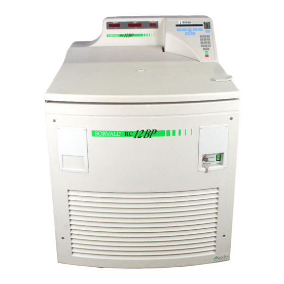
This manual contains information required to operate and maintain the SORVALL RC12BP™ High- Capacity Lowspeed Refrigerated Centrifuge. If you require additional information regarding operation or maintenance, please contact Thermo for assistance. In the United States, call toll-free 1-800-522-7746. Outside the United States, contact your local representative for SORVALL ®... -
Page 10: Parts Location And Identification
Introduction & Description SORVALL ® Centrifuges The RC12BP™ has the following safety features: a protective armor plate steel guard within the cabinet; automatic shutoff of the drive motor for overspeed protection; circuit breakers on the main power and the control panel circuits; and a door interlock which prevents starting the drive while the chamber door is open, or opening the door while the rotor is in motion. - Page 11 RC12 BP™ Introduction & Description • A user-friendly, easy to clean control panel with an interactive backlit LCD SET display that prompts appropriate input and displays advisory messages, option selection indicators, and a separate, large LED RUN display for across-the-room viewing. •...
-
Page 12: Centrifuge Specifications
Introduction & Description SORVALL ® Centrifuges NOTE Selecting BRAKE OFF will affect SLOW STOP. • BRAKE OFF deactivates normal braking for a coasting stop from a user-specified transition speed. • Automatic sample temperature calculation considers the run speed, run time, set temperature and measured chamber tempera- ture to estimate and maintain sample temperature. -
Page 13: Parts Supplied
Wrench, Open-End, 9/16-inch 22001 Preinstallation Kit (supplied separately) Refer to Table 4-1 (on page 4-2), for rotor information. For more ® information, refer to a current SORVALL Product Guide, or contact Thermo or your local representative for SORVALL ® products. -
Page 14: Optional Computer Interface Package
Introduction & Description SORVALL ® Centrifuges Optional Computer Interface Package An optional Network Computer Interface Package (Catalog No. 77017 for 100-120Vac; Catalog No. 77018 for 200-240Vac) is available for use of the QC RUN feature and automatic run data logging. The requirements for the user-supplied computer are: ®... -
Page 15: Chapter 2. Installation
The centrifuge can be dam- on the nameplate, do not connect the power cord and operate the aged if it is connected to the wrong centrifuge or damage to the centrifuge may result. Contact Thermo or voltage. Check the voltage listed on ®... -
Page 16: Location
Installation SORVALL ® Centrifuges Single phase RC12BP™ Centrifuges are equipped with a three-wire cord with three-prong connector to fit a NEMA 6-50P (50A, 2-pole and earth, 1Ø) receptacle, or, on 230V 50Hz centrifuges, a CEE-17 (63A, 2-pole and earth, 1Ø) receptacle. 230V 50Hz polyphase RC12BP™... -
Page 17: Installation
RC12 BP™ Installation Figure 2-2. Centrifuge Dimensions Installation A Preinstallation Kit (Catalog No. 22001) is supplied for UL/CE compliance. Install the Preinstallation Kit according to instructions supplied with the kit. To install the RC12BP™: Position the RC12BP™ in an operating location that satisfies the criteria specified in the previous Location paragraph. -
Page 18: Front Locking Stabilizer Adjustment
Control, Timer, and Temperature Control. NOTE If the centrifuge is to be connected with the optional Network Computer Interface Package for automatic qual- ity control and run logging capability, Thermo or a local ® representative for SORVALL products will install the package components as described in the WatchLog Network™... - Page 19 RC12 BP™ Controls, Indicators, and Displays Chapter 3: CONTROLS, DISPLAYS and INDICATORS The RC12BP™ controls, displays and indicators have been designed for ease of use – the control panel (figure 3-1) allows entry with visual verification of set parameters and current conditions, prompts action if an entry is inappropriate (remains blinking), and communicates status with user messages.
-
Page 20: Run Display
Controls, Indicators, and Displays SORVALL ® Centrifuges RUN Display The RUN display is to the left of the control panel, and is comprised of three fields of large red LEDs that indicate the current measured/ calculated conditions during a run: •... -
Page 21: Set Display
RC12 BP™ Controls, Indicators, and Displays Between runs, the RUN display shows the previous run duration value, viewable in each control mode: – TIME shows the MIN:SEC value at termination (the SET display shows the last TIME input value). – HOLD shows the MIN:SEC value after deceleration to zero. –... -
Page 22: Main Power And Keypad Lock
Controls, Indicators, and Displays SORVALL ® Centrifuges Main POWER and KEYPAD LOCK RUN SINGLE PROGRAM FULL FUNCTION RUN ANY PROGRAM KEYPAD LOCK POWER The Main POWER and KEYPAD LOCK panel is located away from the control console, in the top-right corner of the front cabinet panel. The POWER I/O (ON/OFF) switch is a 50-amp circuit breaker that turns the centrifuge ON and OFF by connecting or disconnecting the main supply power from all system circuitry. -
Page 23: Primary Function Keys And Home Screen Fields
RC12 BP™ Controls, Indicators, and Displays Primary .unction Keys and HOME Screen .ields TIME TEMP ROTOR RECALL SPEED HOLD The Primary Function Keys are the keys below the SET display. Each key is positioned below a corresponding field in the HOME screen, allowing simple, direct access to basic run parameter controls: ROTOR (reserved for future use) would be pressed to specify a different rotor than the one shown in the SET display, which would... - Page 24 Controls, Indicators, and Displays SORVALL ® Centrifuges NOTE When changing mode, rpm/RCF values may appear a digit or two off from the original set value. The centrifuge translates set RCF values to rpm whole numbers for speed control purposes, then calculates that rpm whole number to the closest RCF value.
- Page 25 RC12 BP™ Controls, Indicators, and Displays During a run, to view in an alternative duration control mode (for example, to monitor accumulating TIME when an ACE run is in progress), press one of the other two duration control keys once – this changes the RUN display to show an accumulating value in that alternative mode without altering the way duration is controlled.
-
Page 26: Menu Key And Options
Controls, Indicators, and Displays SORVALL ® Centrifuges MENU Key and OPTIONS The MENU key accesses advanced feature options listed above it, plus other features such as saving parameters to memory. After pressing MENU, pressing 1 accesses a secondary screen to view or enter values, plus confirm option selection;... - Page 27 RC12 BP™ Controls, Indicators, and Displays If, during the QC RUN, an observed RUN display temperature is not within ±2°C of SET temperature (as could be the case when there is a significant temperature change with a short run), the centrifuge will continue to repeat that step of the QC RUN sequence until the observed temperature is within range.
- Page 28 Controls, Indicators, and Displays SORVALL ® Centrifuges establishing blood bank protocols, for optimized braking with minimal resuspension, we recommend starting at setting 5 and adjusting up or down as needed. Selection of BRAKE OFF will have an affect on SLOW STOP (see the NOTE under BRAKE OFF). •...
- Page 29 RC12 BP™ Controls, Indicators, and Displays • CHANGE UNDERTEMPERATURE LIMIT allows changing the minimum allowable sample temperature to establish a new undertemperature offset value. The centrifuge calculates the difference between the set and the minimum temperatures, and retains that value as an offset to apply to future runs, until it is changed.
-
Page 30: Numeric Keypad
Controls, Indicators, and Displays SORVALL ® Centrifuges Numeric Keypad The Numeric Keypad is used to input speed, time, and temperature values into the HOME screen and to select the advanced features. The ENTER key enters newly inputted speed, time, temperature, and RCF values into memory;... -
Page 31: Start And Stop Keys
RC12 BP™ Controls, Indicators, and Displays START and STOP Keys The green START key is used to start the centrifuge run. When the START key is pressed, the green LED status indicator on the key will blink until the rotor begins to spin (which could take up to 20 seconds if SLOW START is selected). -
Page 32: Set Display Advisory Messages
START. If the message reappears when START is pressed, it indicates a door switch failure – remove all sample from the rotor, unplug the centrifuge and contact Thermo Service. DOOR OPEN – RUN NOT STARTED START was pressed, but the centrifuge did not detect that the chamber door was closed. - Page 33 Press CLEAR, turn the main power switch OFF and back ON to see if the fault recurs, then contact Thermo Service. Until the condition is repaired, the centrifuge will not com- municate to WatchLog Network™...
- Page 34 > 35°C, d. centrifuge air inlet blocked or proper clearance not observed (see page 2-2, Location). Check all possible causes before contacting Thermo Service. (WatchLog Network™ record: OVERTEMP.) SAMPLE TEMPERATURE UNDER LIMIT During a run, when the preheat feature was not active (see SAMPLE UNDERTEMP –...
- Page 35 RC12 BP™ Controls, Indicators, and Displays THE SET SPEED EXCEEDS ROTOR MAX - ENTER A LOWER SET SPEED (Future use, if rotors are added.) START was pressed, but the centrifuge detected a set SPEED value that was too high for the SET rotor.
-
Page 36: Terminal Conditions
Runs are disallowed or terminated. These conditions typically cannot be remedied by the user; the centrifuge should be removed from service until it is repaired by Thermo Service. Alternate Tach .ailure During a run, the primary tachometer signal was indicating... - Page 37 A run was in progress when the door closed switch opened, indicating a circuit failure. Remove all sample from the rotor after it stops, then unplug the centrifuge and contact Thermo Service. (WatchLog Network™ record: DOOR.) DOOR LOCK SWITCH .AILURE A run was in progress when the door lock switch opened, indicating a circuit failure.
- Page 38 Fault, a tachometer problem. Wait for the rotor to stop spinning (this could take a few minutes), then use the me- chanical override to remove all sample from the rotor, un- plug the centrifuge and contact Thermo Service. Read the WARNING on page 3-18. (WatchLog Network™ record: DRIVE.) DRIVE .AULT DETECTED –...
- Page 39 (this could take as long as 30 minutes), then use the mechanical override to remove sample from the rotor, unplug the centrifuge and contact Thermo Service. Read the WARNING on page 3-18. (WatchLog Network™ may not record: UNEXPECTED ISR.)
- Page 40 Controls, Indicators, and Displays SORVALL ® Centrifuges...
-
Page 41: Chapter 4. Operation
LEDs to be sure that all segments light. NOTE If any LED segments do not light, note which ones and contact a local Thermo Service Representative. Contin- ued operation when the centrifuge is unable to display all run information correctly could mislead an unaware observer. -
Page 42: Rotor Installation, Loading And Balancing
Operation SORVALL ® Centrifuges Rotor Installation, Loading and Balancing W A R N I N G Install, load, and balance the rotor according to the instructions given in the rotor instruction manual. If maximum compartment mass is exceeded, the maximum speed must be lowered (see Reduc- ing Speed for Rotor Compartment Loads in Excess of Design Mass,... - Page 43 RC12 BP™ Operation NOTE Do not attempt to open the door unless End is in the SPEED display. Doing so when the interlock is to be moving could cause the interlock to bind, requiring cy- cling the main POWER switch several times. Prepare the rotor according to the rotor manual.
-
Page 44: Programmed Operation
Operation SORVALL ® Centrifuges Programmed Operation A. Storing Selections to Program Memory Establish all desired run parameters as explained in steps 1 and 3 of the previous section, Normal Operation. NOTE If you plan on using the QC RUN feature, consider the following as you save runs to program memory: •... - Page 45 RC12 BP™ Operation NOTE To prevent accidental erasure of established programs, if the entered program number has been previously assigned, the following message will appear: IN USE - OVERWRITE? (1=YES, O or ENTER=NO) To review stored programs before overwriting, refer to your Program Log Pad or press RECALL.
-
Page 46: Using Advanced Features (Options)
Operation SORVALL ® Centrifuges Using Advanced .eatures (Options) The advanced features of the RC12BP™ allow for: performing quality control runs, changing speed or time control ranges, changing acceleration/deceleration or overtemperature alert settings, linking- together programmed run parameters, and saving run parameters to program memory for simple recall. - Page 47 RC12 BP™ Operation NOTE Pressing MENU again will return to the HOME SCREEN from anywhere in the advanced feature option screen sequence. Figure 4-1. Advanced Feature Option Screens...
- Page 48 Operation SORVALL ® Centrifuges Use specific options as follows: SELECT QC RUN? The QC RUN feature is considered usable only if the centrifuge is equipped with the optional computer interface package. The connected computer should have WatchLog Network™ soft- ware running before starting a QC RUN. When QC RUN is selected, the SET screen will prompt you to prepare for the run and press START to begin.
- Page 49 RC12 BP™ Operation If, during a QC RUN, the observed RUN temperature is more than 2°C over SET temperature, the DEG C field in the SET display will change to P-COOL. If the temperature is not within 2°C as a program is completed, the centrifuge will automatically repeat that step of the QC sequence.
- Page 50 Operation SORVALL ® Centrifuges SELECT BRAKE O..? This screen allows you to select a speed (in rpm) at which, after termination, deceleration will transition from braking to a coast- ing stop. The amount of time it takes for the rotor to stop depends on the transition speed, windage and inertia of the rotor.
- Page 51 RC12 BP™ Operation CHANGE UNDERTEMPERATURE LIMIT? The RC12BP™ has sample undertemperature protection that will alert the user if the calculated sample temperature in the RUN display is below SET temperature by more than a specified amount. CHANGE UNDERTEMPERATURE LIMIT allows you to specify a minimum allowable sample temperature as it relates to the current SET temperature, to create a new under- temperature offset value that will be applied to future changes to...
-
Page 52: Temperature Control
Operation SORVALL ® Centrifuges So that runs are not inadvertently corrupted, whenever STEP RUN has been selected (indicator lit), changes to run parameters will be ignored unless STEP RUN is deselected before START is pressed. Because of this, the only changes that could be made without deselecting would be if a different step run was recalled from program memory (program numbers 10-15). -
Page 53: Rotor Temperature Equilibration
RC12 BP™ Operation To equilibrate rotor temperature before operation, either store the rotor in a controlled temperature environment (such as refrigerator or cold room), or precool/preheat the rotor in the centrifuge chamber, until the rotor is the same temperature as the sample and the required SET temperature. -
Page 54: Running Hazardous Material
See Chapter 5 for the procedure to follow if a centrifuge or rotor that has been used with a hazardous material must be serviced by Thermo personnel or returned to our service facilities for repair. Reducing Speed for... -
Page 55: Chapter 5. Maintenance
Thermo Service Representative or other Thermo-qualified service personnel. If further service is needed, contact Thermo Service or your local representative for SORVALL ®... -
Page 56: Lubrication
Maintenance SORVALL ® Centrifuges Use 70% ethanol to disinfect the rotor chamber or a 2% glutaralde- C A U T I O N hyde solution to sterilize it. For general radioactive decontamina- Chlorides are extremely tion, use a solution of equal parts of 70% ethanol, water, and 10% harmful to aluminum alloy rotors and SDS. -
Page 57: Customer Control Inspection
If any of these control checks reveal a control inaccuracy, contact Thermo Service or your local representative for SORVALL ® Products to arrange to have a qualified service technician recalibrate the controls. - Page 58 Maintenance SORVALL ® Centrifuges Press START. Using a stopwatch, begin timing precisely as the RUN TIME display counts down to 13:20; then stop timing precisely as the RUN TIME display counts down to 00:00. The stopwatch should read between 13:15 to 13:25, representing 13:20 ±0.5% (4 seconds) plus an additional second to allow for cumulative human error.
-
Page 59: Emergency Sample Recovery
RC12 BP™ Maintenance After termination, immediately after the rotor stops and the door unlocks, open the chamber door and measure the sample temperature using the same calibrated thermometer that was used earlier. The measured sample temperature should be within 2°C of SET temperature. -
Page 60: Parts Ordering Information
W A R N I N G pathogenic material requires servicing by Thermo personnel, either at the customer’s laboratory or at a Thermo facility, comply with the Because of the charac- following procedure to ensure the safety of all personnel:... - Page 61 (what was contaminant and what decontamination method was used). If the centrifuge or rotor must be returned to a Thermo facility: Contact your Thermo representative to obtain a Return Service Order Number (RSO#); be prepared with the name and serial number of the centrifuge or rotor and the repairs required.
- Page 62 Maintenance SORVALL ® Centrifuges...
-
Page 63: Appendix
RC12 BP™ Appendix APPENDIX... -
Page 64: Warranty
SORVALL ® Centrifuges Warranty Thermo Scientific makes no warranty of any kind, expressed or implied, except as stated in this warranty policy. ® The SORVALL RC12BP™ Centrifuge is warranted (subject to the conditions specified below and in the warranty clause of the Thermo... - Page 65 DECONTAMINATION INFORMATION CERTIFICATE Complete and attach to equipment BEFORE servicing (instructions on reverse) PLEASE PRINT DECONTAMINATION CERTIFIED BY _____________________________________________________ TITLE/POSITION ___________________________________________________ PHONE ___________________________ FAX ____________________________ DEPARTMENT _________________________________________________ INSTITUTION _____________________________________________ ADDRESS _________________________________________________________________ CITY _____________________________________________ STATE ____________________________________ ZIP _________________________________ INSTRUMENT ____________________________________________________________________ SERIAL NUMBER _____________________________________ ROTOR _________________________________________________________________________ SERIAL NUMBER _____________________________________ PART ______________________________________________________________________________________...
- Page 66 Thermo our Service facilities and, in our opinion, poses a radioactive or personnel either at the customer's laboratory or at Thermo facilities, biological hazard, the sender will be contacted for instructions as to the following procedure must be complied with to insure safety of disposition of the equipment.
- Page 67 Europea 2002/96EC in merito ai Rifiuti degli Apparecchi Elettrici ed Elettronici (WEEE). È marcato col seguente simbolo. Thermo Scientific ha stipulato contratti con una o diverse società di riciclaggio/smaltimento in ognuno degli Stati Membri Europei. Questo prodotto verrà smaltito o riciclato tramite queste medesime. Ulteriori informazioni sulla conformità...
- Page 68 Wenden Sie sich an Ihren ® products distributor or agent. local des produits SORVALL örtlichen SORVALL -vertreter. ® ® ou leur representant. E-mail Technical Service Representative for SORVALL brand products at ® techsupport.led.asheville@thermofisher.com Visit our web site at http://www.sorvall.com or http://www.thermo.com...
Need help?
Do you have a question about the SORVALL RC-12BP and is the answer not in the manual?
Questions and answers