Sign In
Upload
Download
Table of Contents
Contents
Add to my manuals
Delete from my manuals
Share
URL of this page:
HTML Link:
Bookmark this page
Add
Manual will be automatically added to "My Manuals"
Print this page
×
Bookmark added
×
Added to my manuals
Manuals
Brands
Thermo Manuals
Laboratory Equipment
Forma 3911
Operating and maintenance manual
Thermo Forma 3911 Operating And Maintenance Manual
Environmental chamber
Hide thumbs
1
2
3
4
Table Of Contents
5
6
7
8
9
10
11
12
13
14
15
16
17
18
19
20
21
22
23
24
25
26
27
28
29
30
31
32
33
34
35
page
of
35
Go
/
35
Contents
Table of Contents
Bookmarks
Table of Contents
Table of Contents
Section 1 - Receiving
Preliminary Inspection
Visible Loss or Damage
Responsibility for Shipping Damage
Section 2 - Installation and Set-Up
Location
Choosing the Location
Preliminary Cleaning and Disinfecting
Installing the Shelves
Leveling the Unit
Water (Humidity System) and Drain Connections
Connecting Water Inlet for Humidity System
Alternate Water Supply for Humidity System
Connecting the Drain Line
Remote Data Output
4-20 Milliamp Output
Remote Alarm Contacts
Power Connection
Start-Up
Setting the Overtemp Safety Thermostat
Setting the Undertemp Safety Thermostat
Preparing the (Optional) Cobex Recorder
Installing the Battery
Changing the Chart Paper
Changing the Pen
Honeywell Recorder (Optional)
Connecting the CO2 Source
CO2 Control and Indicators
Section 3 - Start up and Operation
The Control Panel
Setting the Operating Temperature
Setting the Operating Humidity
Air Exchange Ventilator Caps
Heatless Dryer P/N 1900139 (Optional)
Section 4 - Routine Maintenance
Cleaning the Incubator
Maintaining the Humidity Generator
Section 5 - Service
Accessing the Electrical Components
Replacing Over/Undertemp Probe and Thermostat
Replacing the Humidity/Temp Sensor
Programming the Humidity/Temp Controllers
Removing Mechanical Lockout
Removing Software Lockout
Controller Configuration
Offset Calibration (Temp/Humidity)
Replacing the Optional Recorder and Probe(S)
Calibrating the Recorder
Setting the Door Heater Control
CO2 Controller Calibration
Section 6 - Specifications
Section 7 - Spare Parts
Advertisement
Quick Links
Download this manual
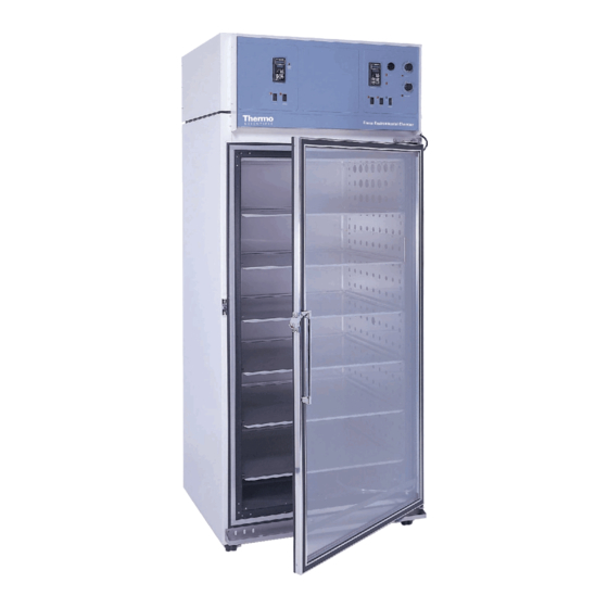
Models: 3911, 3913, 3940 and 3949
Forma Environmental Chamber
Operating and Maintenance Manual
Manual No: 7043940 Rev. 2
Table of
Contents
Previous
Page
Next
Page
1
2
3
4
5
Advertisement
Table of Contents
Need help?
Do you have a question about the Forma 3911 and is the answer not in the manual?
Ask a question
Questions and answers
Related Manuals for Thermo Forma 3911
Laboratory Equipment Thermo FINNPIPETTE DIGITAL Instructions For Use Manual
(16 pages)
Laboratory Equipment Thermo Forma 3940 Operating And Maintenance Manual
Environmental chamber (35 pages)
Laboratory Equipment Thermo Varioskan User Manual
(127 pages)
Laboratory Equipment Thermo 8600 Series Operating And Maintenance Manual
Forma -86c ult freezer (90 pages)
Laboratory Equipment Thermo Savant SpeedVac SPD121P Instruction Manual
Concentrator (16 pages)
Laboratory Equipment Thermo LabSystems Multiskan RC Service Manual
(314 pages)
Laboratory Equipment Thermo Orbitrap Fusion Series Hardware Manual
(118 pages)
Laboratory Equipment Thermo ThermoFlex 900 Manual
Recirculating chiller (90 pages)
Laboratory Equipment Thermo 1284 Series Operating And Maintenance Manual
Class ii, a2 biological safety cabinet (74 pages)
Laboratory Equipment Thermo IEC Centra CL3 Operation Manual
Iec centra cl3 series (24 pages)
Laboratory Equipment Thermo iCAP 6000 Series Hardware Manual
Icp-oes spectrometer (51 pages)
Laboratory Equipment Thermo 2210 Instrument Manual
Sr90/y90 tld-irradiator (23 pages)
Laboratory Equipment Thermo Luminoskan Ascent User Manual
(104 pages)
Laboratory Equipment Thermo IEC Centra CL5 Instruction Manual
(24 pages)
Laboratory Equipment Thermo SORVALL RC-12BP User Manual
(68 pages)
Laboratory Equipment Thermo 4862 Operating And Maintenance Manual
120 volt cell roll unit (31 pages)
This manual is also suitable for:
Forma 3913
Forma 3940
Forma 3949
Table of Contents
Print
Rename the bookmark
Delete bookmark?
Delete from my manuals?
Login
Sign In
OR
Sign in with Facebook
Sign in with Google
Upload manual
Upload from disk
Upload from URL


Need help?
Do you have a question about the Forma 3911 and is the answer not in the manual?
Questions and answers