
Related Manuals for Thermo 1284


Summary of Contents for Thermo 1284
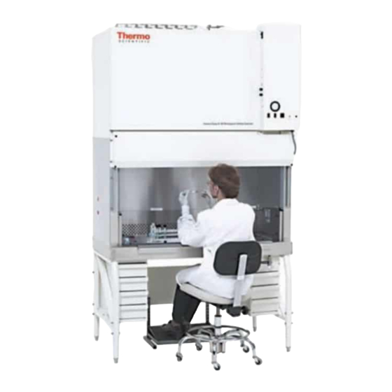
- Page 1 Models: 1284, 1285, 1286 and 1287 Forma Class II, A2 Biological Safety Cabinets Operating and Maintenance Manual Manual No: 7021284 Rev. 1...
- Page 2 Thermo Electron Corporation makes no representa- tions or warranties with respect to this manual. In no event shall Thermo be held liable for any damages, direct or incidental, aris- ing out of or related to the use of this manual.
- Page 3 Class II, A2 Biological Safety Cabinets___________________________________________________________________Safety Alerts the user to important operating and/or maintenance instructions. May be used alone or with other safety sym- bols. Read the accompanying text carefully. Potential electrical hazards. Only qualified persons should perform the instructions and procedures associated with this symbol.
- Page 4 Class II, A2 Biological Safety Cabinets__________________________________________________________________Service...
-
Page 5: Table Of Contents
3.1 Location ........3 - 1 11.1 Model 1284 ......11 - 1 3.2 Power Connection . -
Page 6: Section 1 - Receiving
1.1 Unpacking List 2.1 Description Included with the installation/operation manual are four The Models 1284, 1285, 1286 and 1287 are Class II, Type identification index buttons. These buttons may be used to iden- A2 cabinets. The “Type A2” designation indicates two alterna- tify the type of service supplied to the service valves. -
Page 7: Section 3 - Installation
3.3 Plumbing Connection should be available from the top of the cabinet to the ceiling. Models 1284 and 1285 have one standard service valve Place a bubble-type level on the work surface. Adjust the located on the right side of the work station. Models 1286 and... -
Page 8: Exhaust Requirements
Verify that the building exhaust system is sized to exhaust 30% more air than the cabinet exhausts. Models 1284 and 1285 exhaust an air volume of 358- 391 CFM. Models 1286 and 1287 exhaust an air volume of 531- 580 CFM. - Page 9 Class II, A2 Biological Safety Cabinets_______________________________________________________________Installation Figure 3-2 AIR OR VACUUM INPUT Back of BSC Front of BSC INPUT FOR AIR OR VACUUM 3 - 3...
- Page 10 Figure 3-3...
-
Page 11: Section 4 - Certification Testing
HEPA filters are changed, internal mainte- Certification Companies located under the Services and Support nance is performed, or is relocated. heading at www.thermo.com/forma. If you do not find someone Three industry-related organizations maintain lists of com- listed in your area, please contact the Technical Services panies and individuals who are active in the certification indus- Department for additional references. -
Page 12: Section 5 - Operation
Replace the filters if proper airflow cannot be obtained. The static pressure gauge should not be used as a direct measure of airflow. 4 ft. Series, Models 1284 and 1285 Figure 5-2 5 - 1... - Page 13 Service Valves - Models 1284 and 1285 have one standard serv- ice valve located on the right side of the cabinet. Models 1286 and 1287 have two standard service valves located on the right and left side of the workstation.
-
Page 14: Section 6 - General Cautions And Cleaning
Class II, A2 Biological Safety Cabinets_______________________________General Cautions and Cleaning / Cabinet Start-Up Section 7 - Cabinet Start-Up Section 6 - General Cautions and Cleaning 6.1 Caution Notes 7.1 General Recommendations • Keep movement in the room to a minimum when the cabi- •... -
Page 15: Section 8 - Troubleshooting
Class II, A2 Biological Safety Cabinets___________________________________________________________Troubleshooting Section 8 - Troubleshooting Problem 3: Fluorescent light malfunction Possible causes: 8.1 Troubleshooting Guide • Check lamp pins and socket ends for contact. • Lamp is defective. The following is a guide to troubleshooting the system. If a Problem 4: Loud screeching noise contaminated area of the cabinet must be entered to determine and/or resolve the source of a particular problem, the cabinet... -
Page 16: Section 9 - Routine Maintenance
Class II, A2 Biological Safety Cabinets_______________________________________________________Routine Maintenance 9.3 Adjusting the Damper Section 9 - Routine Maintenance Since the HEPA filter resistance may vary from filter to fil- ter (even filters of the same size), a damper has been installed Before any maintenance work is performed in in the cabinet exhaust system for maintaining proper airflow the biological safety cabinet, the unit must first balance. -
Page 17: Biological Safety Cabinet Test Grids
Class II, A2 Biological Safety Cabinets_______________________________________________________Routine Maintenance 9.4 Biological Safety Cabinet Test Grids a. 4-foot Series, Models 1284 and 1285 Figure 9-2 If it is determined that the damper must be adjusted in order for the proper airflow balance to be maintained, adjust it as follows: 1. -
Page 18: Blower Control
Refer to Figure 4-5. 9.6 Receptacle Fuses Receptacle Fuses (7 Amp - Models 1284/1285, 3 Amp - Models 1286/1287) - The receptacle fuses (2), located directly below the blower motor/lights Reset button, are for the recepta- cles only. -
Page 19: Section 10 - Service
10. Remove the plenum access panel. Remove the 1/4 nuts 8. Pry the pressure plate loose from the gasket and set it to and all threads (2 front, 2 back for 1284/1285)(3 front, 3 the side. back for 1286/1287) securing the panel. Lift and remove the panel. - Page 20 Class II, A2 Biological Safety Cabinets__________________________________________________________________Service 10. Release the two latches securing the supply plenum to the blower housing. 11. Disconnect the vinyl tubing that connects the Mag gauge to the plenum. 12. Remove the hex nuts (4 on the four-foot models, 6 on the six-foot models), springs, washers and hold-down brackets securing the plenum.
- Page 21 Class II, A2 Biological Safety Cabinets___________________________________________________________Specifications Section 11 – Specifications 11.1 Models - 1284 and 1285 (4’ Cabinet with Sliding 11.2 Models - 1286 and 1287 (6’ Cabinet with Sliding Window) Window) Construction Work Surface: Type 304 Construction Work Surface: Type 304...
-
Page 22: Environmental Conditions
Class II, A2 Biological Safety Cabinets____________________________________________________________Specifications 11.3 Environmental Conditions The biological safety cabinets are designed to be electrically safe in the following environmental conditions: • Indoors • Altitude: Up to 2,000 meters • Temperature: 5°C to 43°C • Humidity: 80% RH at or below 31°C, decreasing linearly to 50% RH at 40°C •... - Page 23 MODEL (S): 1284, 1285 Test Voltage: 115, 230 Frequency: 60, 50 Hz FLA: Magnehelic Gauge Reading Damper Position: Position from "Open" (Test points on speed control board - Terminal "N" neutral and Terminal "M" motor.) True RMS Voltage To motor: NOTE: Use True RMS volt meter.
- Page 24 MODEL (S): 1286, 1287 Test Voltage: 115, 230 Frequency: 60, 50 Hz FLA: Magnehelic Gauge Reading Damper Position: Position from "Open" (Test points on speed control board - Terminal "N" neutral and Terminal "M" motor.) True RMS Voltage To motor: NOTE: Use True RMS volt meter.
-
Page 27: Section 12 - Accessories
Class II, A2 Biological Safety Cabinets_____________________________________________________Accessories / Parts List Section 12 - Accessories Section 13 - Parts List Description Order Number 13.1 Model 1284 Service Valve 191275 Stock # Description Armrest, 4’ cabinet 191509 Armrest, 6’ cabinet 191512 156106 3/4 HP Blower Motor (1625 RPM) -
Page 28: Model 1286
Class II, A2 Biological Safety Cabinets________________________________________________________________Parts List 13.2 Model 1286 13.3 Filter Pressure Drop Conversion Stock # Description Pressure drop across a HEPA filter is linear which allows one to accurately predict the pressure drop at various CFM if 156109 HP Blower Motor (1500 RPM) given a starting value. - Page 29 Class II, A2 Biological Safety Cabinets______________________________________________________ Electrical Schematics 14 -1...
- Page 30 Class II, A2 Biological Safety Cabinets______________________________________________________ Electrical Schematics 14 -2...
- Page 31 Class II, A2 Biological Safety Cabinets______________________________________________________ Electrical Schematics 14 -3...
- Page 32 Class II, A2 Biological Safety Cabinets______________________________________________________ Electrical Schematics 14 -4...
- Page 33 Class II, A2 Biological Safety Cabinets______________________________________________________ Electrical Schematics 14 -5...
- Page 34 Class II, A2 Biological Safety Cabinets______________________________________________________ Electrical Schematics 14 -6...
- Page 35 Class II, A2 Biological Safety Cabinets______________________________________________________ Electrical Schematics 14 -7...
- Page 36 Class II, A2 Biological Safety Cabinets______________________________________________________ Electrical Schematics 14 -8...
- Page 37 Class II, A2 Biological Safety Cabinets______________________________________________________ Electrical Schematics 14 -9...
- Page 38 Class II, A2 Biological Safety Cabinets______________________________________________________ Electrical Schematics 14 -10...
- Page 39 Class II, A2 Biological Safety Cabinets______________________________________________________ Electrical Schematics 14 -11...
- Page 40 Class II, A2 Biological Safety Cabinets______________________________________________________ Electrical Schematics 14 -12...
-
Page 41: Section 15 - Warranty
Your local Thermo Sales Office is ready to help with comprehensive site preparation information before your equipment arrives. Printed instruction manuals carefully detail equipment installation, operation and preventive maintenance. - Page 42 The Technical Services Department must give prior approval for return of any component or equipment. At Thermo’s option, all non-conforming parts must be returned to Thermo postage paid and replacement parts are shipped FOB destination.
- Page 43 Fax (919) 787-4916 http://www.cetainternational.org/members/corp_indiv.htm For your convenience we have included a partial list of agencies that perform certification on our website. If you do not find someone listed in your area, please contact Thermo Forma’s technical services department for additional references.
- Page 44 Thermo Electron Corporation Controlled Environment Corporation Millcreek Road, P.O. Box 649 Marietta, Ohio 45750 U.S.A. Telephone (740) 373-4763 Telefax (740) 373-4189...
Need help?
Do you have a question about the 1284 and is the answer not in the manual?
Questions and answers