Table of Contents
Advertisement
Quick Links
Advertisement
Table of Contents

Related Manuals for Nautilus 637-8806


Summary of Contents for Nautilus 637-8806
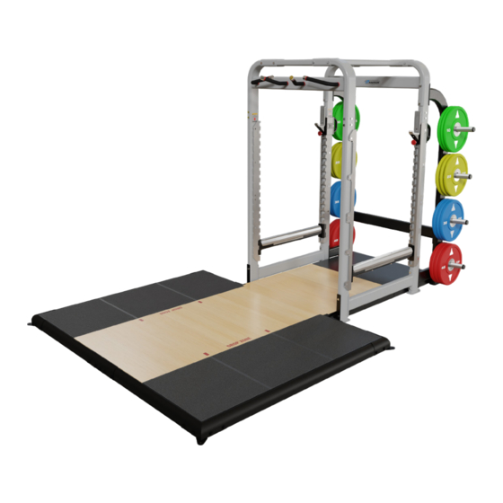
- Page 1 CORE HEALTH & FITNESS POWER RACK & SVA COMBO OWNER'S MANUAL CONTACT SUPPORT NOW...
-
Page 2: Table Of Contents
TABLE OF CONTENTS IMPORTANT SAFETY INSTRUCTIONS ........................2 IMPORTANT LABEL LOCATIONS ........................4 PRODUCT SPECIFICATIONS ..............4 ASSEMBLY ........................7 PROCEDURE ..............8 MAINTENANCE ........................27 TOOLS ..............27 MAINTENANCE SCHEDULE ..............28 SUPPORT & SERVICE ........................29 Page 1... -
Page 3: Important Safety Instructions
Use only replacement components supplied by Leave a minimum of 19.7 inches (0.5 meters) Nautilus®. Substitutes are forbidden and will void between two adjacent units. These dimensions all warranties. are the recommended minimum distances. - Page 4 12. It is the purchaser’s sole responsibility to properly instruct its end users and supervising personnel as to the proper operating procedures of all Nautilus equipment. 13. After assembly, a complete visual inspection, and test of the features and functions of the assembled unit must be made prior to use.
-
Page 5: Important Label Locations
IMPORTANT LABEL LOCATIONS This page shows the location of the warning labels and communication stickers placed on the equipment as part of the manufacturing process. It is critical that owners maintain the integrity and placement of these stickers. If you find any stickers missing or damaged the replacement numbers are shown on the support site and following pages. - Page 6 CAUTION OVERHEAD CLEARANCE 731-0517 050-5845 STICKER, WARNING, BOLT DOWN LABEL, OVERHEAD CLEARANCE ADJUST BAR HOOK For Your Safety Ensure Full Engagement Of Pull-pin. Vergewissern Sie sich zu Ihrer eigenen Sicherheit, dass der Feststellbolzen vollständig eingerastet ist Assurez votre propre sécurité, que la goupille de verrouillage est pleinement engagée 731-4997 STICKER,WARNING,BAR HOOK,POWER RACK...
- Page 7 731-7311 731-7322 STICKER,NAUTILUS, DECO,45MMX191MM STICKER,NAUTILUS,70MM 731-5002 731-5003 STICKER,WARNING,USE SPOTTER STICKER,WARNING,PROPER PLACE 731-5103 731-4977 STICKER,WARNING,MAXIMUM WEIGHT STICKER,NAME,POWER RACK Notice: images are not to scale Page 6...
-
Page 8: Assembly
ASSEMBLY Metric Steel Bolts Torque Specifications Bolt Size Thread Pitch Torque, N-m (lbs-ft) All equipment MUST be secured 1.25 10 to13.5 (8 to10) (bolted and tightened) to a solid, level surface, using all of the anchoring 1.25 25.5 to 28.5 (19 to 21) holes provided, to stabilize and 10mm 1.75... -
Page 9: Procedure
PROCEDURE 731-4993-XX 731-4970-XX 731-2420 731-2419 731-4996-XX 731-2315-XX 731-2419 731-2398 Fig. 5 1. Take the front and back upper weldments and place them on a soft surface. (A moving blanket will help reduce damage from hard surfaces) 2. Lay cross weldments between the upper weldments. 3. - Page 10 731-4975-XX 731-4976-XX 731-4976-XX 731-4975-XX 731-2333 731-2419 Fig. 6 4. Take the four uprights and slide the onto the correct post sleeve. See Fig. 6. Note: When assembled correctly, all mounting holes are to the inside of the as shown. 5. Attach each upright with six bolts 731-2333 and six washers 731-2419. Fully tighten. Page 9...
- Page 11 Fig. 7 DANGER: Unit is heavy. At least two persons are required for steps 6 & 7. 6. Lay assembly on its side. Support the legs as you rotate assembly, do not allow to drop freely. 7. Lift top of assembly to upright the Main frame. Page 10...
- Page 12 731-2315-XX 731-9082 731-2398 731-2419 731-2420 731-9090 731-9098 731-4970-XX Fig. 8 8. Move frame assembly to final position. 10’ (3m) free space for the platform assembly in front of the frame assembly is recommended. Tech Tip: Installers who have previously installed a Power Rack will note that there are no plastic feet included in the instructions.
- Page 13 731-2377-XX 731-4972-XX 731-0363 731-0367 731-2400 Fig. 9 11. Connect but do not fully tighten back crossbrace 731-4972-XX to weight holder weldment with four bolts 731-2400, eight washers 731-0367 and four nuts 731-0363 through brackets 731-2377-XX as shown. 12. Tighten all frame hardware from step 9, step 10, & step 11. Page 12...
- Page 14 PREDRILL 731-0585 740-7897 27-0366 731-9097 Fig. 10 13. Install the trim tension rod into the rear of the top dampening platform with the nut towards the frame. 14. Place edge bands 731-9089 and predrill at each screw location. 15. Install edge bands with three screws 740-7897 and three washers 731-0585 each. 16.
- Page 15 Fig. 11 17. Move the center platform assembly into position between frame. 18. Slide the center platform into position up against the top platform assembly - ensure that the extension rod threads into the barrel nut on the underside of the platform. Page 14...
- Page 16 120-3411 731-9095 731-9096 Fig. 12 19. Thread the tension rod 731-9096 through washer 120-3411, through the back of the spotter plate 731- 9095. 20. Slide all platform parts together and make sure there are no gaps in the platforms and that the sides are flush.
- Page 17 731-8804 731-8810 731-8809 731-0357 731-2354 731-8808 Fig. 13 22. Connect the left plug 731-8810 into tube 731-8807. 23. Connect the right plug 731-8809 into tube 731-8806. 24. Connect each assembly to frame with a bolt 110-4357 and washer 731-0357. Page 16...
- Page 18 731-8812 731-8806 110-3621 731-0357 731-8802 Fig. 14 25. Connect the front sleeve 731-8812 with two nut plates 731-8806 with two bolts 110-3621 and two washers 731-0357 each, do not fully tighten. 26. Slide the tubes 731-8802 through the loose nut plate and secure finger tight. Page 17...
- Page 19 01-9337 04-2032 731-0357 Fig. 15 View from below 27. Connect the front bracket assembly to the platform with bolt 01-9337 through washers 04-2032 and 731-0357. Ensure that the bolt properly engages with the barrel nut on the underside of the platform. Do not fully tighten.
- Page 20 731-8797 731-8806 731-8801 Fig. 16 28. Fill in installation date on each side tube sticker 12-7051. 29. Assemble left and right sides using two nut plates 731-8806 with two bolts 110-3621 and two washers 731-0357 each, do not fully tighten. 30.
- Page 21 27-0963 110-3621 731-0357 Fig. 17 31. Slide left and right sides through front and rear tube then secure loosely with two bolts 110-3621 and two washers 731-0357 each. 32. Install the six polyurethane rebond foam pads 27-0963 into the platform frame. Page 20...
- Page 22 27-0962 Fig. 18 33. Install the six middle pads 27-0962 onto the top of the rebond foam pads. Page 21...
- Page 23 27-0760 Fig. 19 34. Install the rubber mat wings 27-0760 textured side up, onto the top of the middle pads. 35. Fully tighten all platform hardware. Page 22...
- Page 24 731-5259 731-0365 731-0355 110-4358 731-2299-XX Fig. 20 36. Install the eight weight horns to the rack angled up. Insert the weldment through the frame. The notches on the tube should be at the top. Secure weldment with two bolts 110-4358 through plate 731-2299-XX with two washers 731-0355 and nuts 731-0365.
- Page 25 Fig. 21 37. Install Bar Catches. Bar Catches can be used on either the front or back uprights. Note: When using the Bar Catches make sure they are installed on the machine at the same level and that they are fully engaged in the mounting position. Ensure the safety pin is engaged. To use: Grab Bar Catch with both hands, one on the handle and the other on the pull pin.
- Page 26 Fig. 22 38. Install Safety Stops To use: Grab the Safety Stop with two hands close to the mounting plates, lift the stop straight up and then towards you. Move the Safety Stop to the desired location for your exercise, push the stop into the slots on the mounting plate, then push the stop down and make sure they are fully seated into the slot.
- Page 27 Fig. 23 Assembly is complete. Page 26...
-
Page 28: Maintenance
MAINTENANCE TOOLS Working on this product will require basic and/or sometimes specialty tools based on the type of service that will be performed at any time. To assist, we recommend having the tools listed available when performing maintenance. Tool Metric Allen Key Set Screwdriver Set, Phillips Metric Open-Ended Wrench Set Screwdriver Set, Flat... -
Page 29: Maintenance Schedule
MAINTENANCE SCHEDULE With durable, high performance components, this equipment is designed for heavy usage with minimal maintenance required. To keep it in top condition, perform regular daily, weekly and monthly preventive maintenance routines outlined below. The safety and integrity of this machine can only be maintained when the equipment is regularly examined for damage and wear and repaired. -
Page 30: Support & Service
SUPPORT & SERVICE CORE CONNECT Core Connect is your portal to all things service! Whether you need to order parts or register your warranty, Core Connect is the most effective way to get what you need fast and keep your facility operating smoothly. OFFERS 24-HOUR SELF SERVICE ACCESS TO: •... - Page 31 PART NUMBER 637-8806, REV B All rights reserved. Star Trac, the Star Trac logo and StairMaster are registered trademarks of Core Health & Fitness, LLC. Schwinn and Nautilus are registered trademarks of Nautilus Inc. used under license to Core Health & Fitness LLC. Throwdown is a registered trademark of Throwdown Industries, LLC.
Need help?
Do you have a question about the 637-8806 and is the answer not in the manual?
Questions and answers