
Related Manuals for Meritor MS-113


Summary of Contents for Meritor MS-113
- Page 1 Issued 07-02 $2.50 Rear Axle Single-Reduction Carrier Model MS-113 Maintenance Manual MM-0230...
- Page 2 Service Notes Information in the DriveTrain Plus This manual provides instructions for Meritor’s ArvinMeritor Tech Library on our Web model MS-113 single-reduction rear axle. Before Site you begin procedures: Enter the following address in your browser’s 1. Read and understand all instructions and address box.
-
Page 3: Table Of Contents
Removing Fasteners Secured with Adhesive ..........13 Install Fasteners New Fasteners with Pre-Applied Adhesive Original or Used Fasteners Using Meritor Liquid Adhesive 2297-C-7049 or ® Loctite 680 Adhesive, or Equivalent Applying Meritor Specification 2297-T-4180 Adhesive in the Bearing Bores Differential... - Page 4 Table of Contents Section 5: Diagnostics Vehicle Will Not Move ..............29 Differential Making Noise .
-
Page 5: Exploded View
Exploded View Exploded View Locknut, M32 x 1.5 13 Inner Bearing Cup 25 Side Gear Yoke 14 Carrier 26 Differential Pinion Shaft Seal 15 Differential Cap Capscrew, M14 x 2.0 27 Differential Case Screws, M6 x 1.0 16 Cotter Pins 28 Differential Case Capscrew, M12 x 1.75 Lock Plate 17 Thrust Washer... -
Page 6: Section 1: Introduction
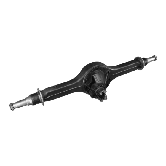
Section 1 Introduction Section 1 Introduction Meritor’s model MS-113 single-reduction rear axle has a single-reduction carrier, which is front-mounted into the axle housing. Figure 1.1 . The carrier has a hypoid drive pinion and ring gear set. Bevel gears are used in the differential assembly. -
Page 7: Section 2: Removal And Disassembly
Section 2 Removal and Disassembly Section 2 Removal and Disassembly Figure 2.2 WARNING EASY SERVICE To prevent serious eye injury, always wear safe eye protection when you perform vehicle maintenance or service. Park the vehicle on a level surface. Block the wheels to prevent the vehicle from moving. -
Page 8: Differential Carrier From The Axle Housing
Section 2 Removal and Disassembly 6. Remove the capscrews from the flanges of 3. Loosen the two capscrews in the TOP of the both axle shafts. Figure 2.3 . carrier, but do not remove them. 7. Mark each axle shaft before you remove it 4. -
Page 9: Differential Case And Ring Gear From The Carrier
Section 2 Removal and Disassembly Differential Case and Ring Gear from the Figure 2.8 Carrier NOTE: Before working on the differential carrier, inspect the gear set for damage. If the gear set is not damaged, it can be reused. Measure the backlash of the gear set and record the dimension. -
Page 10: Disassembly
Section 2 Removal and Disassembly Figure 2.10 Figure 2.12 1 YOKE BAR 1 CAPSCREW 2 LOCK PLATE Figure 2.11 Disassembly WARNING Observe all warnings and cautions provided by the press manufacturer to avoid damage to components and serious personal injury. Differential Case and Ring Gear 1. - Page 11 Section 2 Removal and Disassembly 2. Separate the differential case halves. Figure 2.16 Figure 2.14 . Remove the thrust washer and side gear. Figure 2.15 . 3. Remove the differential pinion shaft, differential pinions and thrust washers. Figure 2.16 . 4.
-
Page 12: Drive Pinion
Section 2 Removal and Disassembly 5. Use a bearing puller or a press to remove the bearing cones from both halves of the differential case. Figure 2.19. Figure 2.19 1 DIFFERENTIAL CASE Drive Pinion 1. Remove and discard the pinion cage O-ring. Figure 2.20. -
Page 13: Section 3: Prepare Parts For Assembly
Section 3 Prepare Parts for Assembly Clean Rough Parts Section 3 Prepare Parts for Assembly WARNING 1. Clean rough parts with the same method as To prevent serious eye injury, always wear safe cleaning ground and polished parts. eye protection when you perform vehicle 2. -
Page 14: Inspect Parts
Section 3 Prepare Parts for Assembly Inspect Parts Figure 3.2 It is very important to inspect all parts carefully and completely before the axle or carrier is assembled. Check all parts for wear and replace damaged parts. 1. Inspect the cup, cone, rollers and cage of all tapered roller bearings in the assembly. -
Page 15: Repair Or Replace Parts
Section 3 Prepare Parts for Assembly Figure 3.5 Figure 3.6 1 CASE HALVES 2 PINION AND THRUST WASHER 3 SIDE GEAR AND THRUST WASHER SPALLING AND FLAKING 4 DIFFERENTIAL PINION SHAFT Repair or Replace Parts CAUTION A drive pinion and ring gear is machined as a NOTE: Threads must be without damage and matched set. -
Page 16: Repair Welding On Axle Housings
Meritor Drive Axle Housings 2. Remove the differential carrier from the axle Refer to Maintenance Manual 8, Drive Axle housing. Refer to the correct Meritor carrier Housings. To obtain this publication, refer to the maintenance manual or the vehicle Service Notes page on the front inside cover of manufacturer’s instructions. -
Page 17: Do Not Bend Or Straighten A Damaged Drive Axle Housing
Do not bend, repair or recondition LOWER BRACKET axle components by welding or heat-treating. A bent axle beam reduces axle strength, affects vehicle operation and voids Meritor’s warranty. Figure 3.10 Serious personal injury and damage to components can result. -
Page 18: Removing Fasteners Secured With Adhesive
Section 3 Prepare Parts for Assembly Removing Fasteners Secured with 2. Apply four or five drops of Meritor liquid ® adhesive, Loctite 680 adhesive, or equivalent, Adhesive inside each threaded hole or bore. Do not apply adhesive directly to fastener threads. -
Page 19: Applying Three Bond 1216, Or Equivalent, Silicone Gasket Material
flush them with water for 15 minutes. Have your eyes checked by a physician as soon as possible. NOTE: The following silicone gasket products or equivalent can be used for Meritor components: Three Bond Liquid Gasket number TB 1216 (Grey) ®... -
Page 20: Gear Sets
Gear Set Match Number you will install has matched parts. Figure 3.15. NOTE: Meritor’s drive pinions and ring gears are only available as matched sets. Each gear in a set has an alpha-numeric match number. - Page 21 Section 3 Prepare Parts for Assembly Pinion Cone Variation Number NOTE: Don’t use the pinion cone variation number when you check for a matched gear set. Use this number when you adjust the pinion depth in the carrier. Refer to Section 4. Pinion Cone (PC) Variation Drive Pinion...
-
Page 22: Section 4: Assembly And Installation
2. Heat the ring gear. A maximum temperature of Drive Pinion 340°F (170°C) can be applied at the gear web. 1. Apply Meritor specification 2297-W-4287, The temperature at the gear teeth must not 2297-U-4519 or 076328-4 lubricant to the new exceed 250°F (120°C). - Page 23 Section 4 Assembly and Installation 9. Install the thrust washer and side gear into the Figure 4.4 differential case. Figure 4.2. 10. Slide the differential pinions and thrust washers onto the differential pinion shaft. Figure 4.3. 11. Position the differential pinion shaft in the differential case on top of the side gear.
-
Page 24: Differential Gears Rotating Resistance
Section 4 Assembly and Installation 14. Install the capscrews through both differential 2. Place the differential and ring gear assembly case halves and into the ring gear. Use a in a vise. Install soft metal covers over the vise CRISSCROSS pattern to tighten the capscrews jaws to protect the ring gear. -
Page 25: Differential Case And Ring Gear Into The Carrier
Section 4 Assembly and Installation 11. Use appropriate tools to screw the pinion cage 15. Install the yoke and locknut onto the drive into the carrier while rotating the pinion to pinion shaft. seat the bearings. 16. Fasten a yoke bar to the yoke to hold the drive 12. -
Page 26: Adjust Differential Bearing Preload
Section 4 Assembly and Installation Adjust Differential Bearing Preload 3. Use one of the following procedures to move the differential and ring gear to the LEFT and Use Method 1 or Method 2 below to adjust RIGHT while you read the dial indicator. differential bearing preload. -
Page 27: Check Ring Gear Runout (Radial Movement)
Section 4 Assembly and Installation Method 2 5. Subtract the measurement you obtained in Step 2 from the measurement in Step 4. The 1. Hand-tighten both adjusting rings against the difference is the amount the bearing caps have differential bearings. expanded. -
Page 28: Ring Gear Backlash
Section 4 Assembly and Installation 3. Rotate the differential and ring gear. Read 3. Adjust the dial indicator to ZERO. Hold the the dial indicator. Runout must not exceed drive pinion in position. 0.008-inch (0.200 mm). 4. After reading the dial indicator, rotate the differential and ring gear a small amount in If runout exceeds the specification above: both directions against the drive pinion teeth. -
Page 29: Check The Tooth Contact Patterns (Backlash) Of The Gear Set
Section 4 Assembly and Installation NOTE: When you adjust backlash, only move the 1. Adjust the backlash of a new gear set to ring gear. Do not move the drive pinion. 0.005-0.015-inch (0.13-0.38 mm). Adjust the backlash of an old gear set to the setting that you measured before the carrier was 6. - Page 30 Section 4 Assembly and Installation Figure 4.25 Figure 4.28 1 GOOD HAND-ROLLED PATTERN 1 GOOD PATTERN IN OPERATION — GENEROID GEARS A high contact pattern indicates that the drive Figure 4.26 pinion was not installed deep enough into the carrier. A low contact pattern indicates that the drive pinion was installed too deep in the carrier.
- Page 31 Section 4 Assembly and Installation 6. Adjust the backlash of the ring gear within the 7. Install the cotter pins into the adjusting rings specification range to move the contact so that the large end is between the adjusting patterns to the correct location in the length of ring lugs.
-
Page 32: Differential Carrier Into The Axle Housing
83-110 lb-ft (110-150 N•m). replace the axle housing. Refer to Section 3. 9. Install the remaining capscrews and tighten 3. Apply Meritor specification 2297-T-4180 liquid them to 83-110 lb-ft (110-150 N•m). adhesive, or equivalent, into the threaded holes in the axle housing. To obtain this adhesive, refer to the Service Notes page on the front inside cover of this manual. -
Page 33: Axle Shafts In The Axle Assembly
Section 4 Assembly and Installation Axle Shafts in the Axle Assembly 5. Road test the vehicle in an unloaded condition for one to two miles (1.6-3.2 km). Do not 1. Clean the mating surfaces of the axle shaft exceed 25 mph (40 km/h). flange and the wheel hub. -
Page 34: Section 5: Diagnostics
Section 5 Diagnostics Vehicle Will Not Move Section 5 Diagnostics Visually inspect the carrier in the axle housing. When the carrier is When the carrier is Backlash reassembled later, reassembled later, set Remove the within spec? set the backlash to the backlash to spec. -
Page 35: Differential Making Noise
Section 5 Diagnostics Differential Making Noise Visually inspect the carrier in the axle housing. When the carrier is When the carrier is Backlash reassembled later, reassembled later, set within spec? set the backlash to Remove the carrier the backlash to spec. the recorded reading. -
Page 36: Oil Leak
Inspect the axle housing Clean the seal area. welds for cracks or leaks. Joint If you find weld cracks, leaking? contact Meritor for repair welding procedures. Test drive the vehicle to confirm that the leak is repaired. Drain and inspect Return the vehicle to the lubricant. -
Page 37: Contaminated Lubricant Found During Preventive Maintenance
Inspect the axle housing Replace the pinion welds for cracks or leaks. Joint If you find weld cracks, seal with a leaking? contact Meritor for unitized seal. repair welding procedures. Replace the pinion cage O-ring with a new O-ring. Drain and inspect the lubricant. -
Page 38: Section 6: Torque Specifications
Section 6 Torque Specifications Section 6 Torque Specifications Description Specification Pinion Bearing Preload Rolling Torque 5-20 lb-in (5.8-23.0 N•cm) Differential Bearing Preload 15-35 lb-in (1.7-3.5 N•m) Expansion Between Bearing Caps 0.006-0.013-inch (0.15-0.33 mm) Differential Gears Rotating Resistance 50 lb-ft (68 N•m) Ring Gear Runout 0.008-inch (0.200 mm) maximum... -
Page 39: Section 7: Lubrication
Section 7 Lubrication Section 7 Lubrication For complete information on lubricating drive axles and carriers, refer to Maintenance Manual 1, Lubrication. To obtain this publication, refer to the Service Notes page on the front inside cover of this manual. Lubricant Capacity U.S. - Page 40 Section 7 Lubrication Axle Oil Specifications A.P.I. Meritor Military/SAE Outside Gear Oil Type Specification Grade Specification Specification Temperature Petroleum with GL-5 85W/140 O-76A MIL-PRF-2105E Above +10°F (–12°C) EP Additives 80W/140 O-76B Above –15°F (–26°C) SAE J2360 80W/90 O-76D Above –15°F (–26°C)
-
Page 41: Section 8: Towing Instructions
5. Install a cover over the open end of each hub damage the axles if the wrong procedure is used where an axle shaft was removed. This will before transporting begins. Meritor recommends prevent dirt from entering the bearing cavity that you use the following procedure. -
Page 42: After Towing Or Drive-Away
Section 8 Towing Instructions After Towing or Drive-Away 7. Check the lubricant level in the axles and hubs where the axle shafts were removed. Add the correct type and amount of lubricant if WARNING necessary. For information about lubrication, refer to Maintenance Manual 1, Lubrication, or Engage the parking brake to prevent the vehicle refer to Section 7. -
Page 43: Section 9: Special Tools
Section 9 Special Tools Carrier Repair Stand Specifications Section 9 Special Tools SPX Kent-Moore part number J-3409-D Plates 8’ (2.44 mm) long x 3/4” (19.05 mm) thick x 1-1/4” (31.75 mm) wide with a tongue to fit slot in bar weld plates to bar Handle 7”... -
Page 44: How To Make A Yoke Bar
Section 9 Special Tools How to Make a Yoke Bar Figure 9.2 1. Measure dimensions A and B of the yoke you are servicing. Figure 9.1. Figure 9.1 YOKE BAR YOKE 2. Calculate dimensions C and D of the yoke bar by adding 0.125-0.250-inch (3.175-6.35 mm) to dimensions A and B of the yoke. - Page 45 Information contained in this publication was in effect at the time the publication was approved for printing and is 2135 West Maple Road subject to change without notice or liability. Meritor Heavy Vehicle Systems, LLC, reserves the right to revise the Troy, MI 48084 USA information presented or to discontinue the production of parts described at any time.
Need help?
Do you have a question about the MS-113 and is the answer not in the manual?
Questions and answers