
Related Manuals for Meritor 13Х Series


Summary of Contents for Meritor 13Х Series
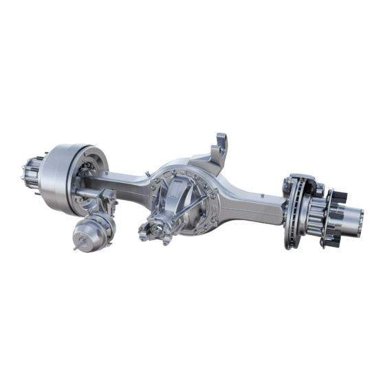
- Page 1 Maintenance Manual MM-15103 13X Series Rear Differential Carrier MS1713X, MS1913X and MS2113X Models Issued 07-17...
- Page 2 Information contained in this publication was in effect at the time the publication was approved for printing and is subject to change without notice or liability. Meritor Heavy Vehicle Systems, LLC, reserves the right to revise the information presented or to discontinue the production of parts described at any time.
-
Page 3: Table Of Contents
Contents Section 1: Exploded View Drive Pinion Shim Pack Thickness Assembly 13X Series Carrier and Axle Housing Assembly “Dry Fit”Assembly of the Drive Pinion to Verify Shim Pack Section 2: Introduction Installation Description Drive Pinion 13X Series Rear Differential Carrier Assembly Stall-Testing Can Damage a Drive Axle Main Differential and Ring Gear... -
Page 4: Section 1: Exploded View
1 Exploded View Figure 1.1 13 17 4011902a Item Description Item Description Yoke Locknut Bearing Cup Flat Washer Capscrew Yoke Hardened Washer Deflector Tapered Dowel Oil Seal Assembly Name Plate Bearing Cone Carrier Housing Meritor Maintenance Manual MM-15103 (Issued 07-17) - Page 5 Flange Case Half Ring Gear Thrust Washer, Flat Side Gear Short Spider Pin Roll Pin Thrust Washer, Spherical Pinion Gear Long Spider Pin Plain Case Half Magnetic Plug Magnets Name Plate Short Axle Shaft Meritor Maintenance Manual MM-15103 (Issued 07-17)
-
Page 6: Section 2: Introduction
13X Series Rear Differential Carrier evaluate vehicle performance, and test the service and park brakes. The Meritor 13X series single rear differential carrier is a During stall-testing, or any similar procedure, the drive axle input single-reduction, front-mounted carrier designed for medium duty receives multiplied torque, which can exceed the specified torque applications. - Page 7 2 Introduction Figure 2.3 CARRIER PART NO. CUSTOMER NO. SERIAL NO. RATIO CARRIER IDENTIFICATION TAG 4008212b Figure 2.3 Refer to Figure 2.4 for an explanation of the model number. Meritor Maintenance Manual MM-15103 (Issued 07-17)
- Page 8 2 Introduction Figure 2.4 Meritor MS-13X Drive Axle Model Nomenclature Housing Wall 0 = Cast 1 = TBD 2 = 0.31 in. (8 mm) 3 = 0.37/0.39 in. (9.5/10.0 mm) GAWR 4 = 0.43 in. (11 mm) 5 = 0.50/0.51 in. (12.7/13.0 mm) xx = GAWR (000) Pounds or Tons 6 = 0.56 in.
-
Page 9: Section 3: Removal And Disassembly
Park the vehicle on a level surface and block the wheels to prevent the vehicle from moving. Raise the end of the vehicle where the axle is mounted. Use a jack or other lifting tool, and place safety stands under each side of the axle. Meritor Maintenance Manual MM-15103 (Issued 07-17) -
Page 10: Axle Shafts
EASY-SERVICE™ BEARING CUPS 20 CAPSCREWS U-JOINT CROSS 21 END YOKE SLIP YOKE 22 SLIP YOKE 10 CAPSCREWS 23 TUBING 11 END YOKE 24 U-JOINT CROSS 12 WELD YOKE 25 WELD YOKE 13 SLIP YOKE Figure 3.2 Meritor Maintenance Manual MM-15103 (Issued 07-17) -
Page 11: Differential Carrier From The Axle Housing
Loosen the differential carrier in the axle housing. Use a leather mallet to hit the mounting flange of the carrier at several points. After the carrier is loosened, remove the top two fasteners. 1002987a Figure 3.5 Meritor Maintenance Manual MM-15103 (Issued 07-17) -
Page 12: Differential And Ring Gear From The Carrier
Step 1 through Step 4 under Ring Gear Tooth Contact Pattern, Backlash in Section 5 for instructions. Adjust backlash to the original dimension when you install the gear set into the carrier during assembly procedures. Meritor Maintenance Manual MM-15103 (Issued 07-17) - Page 13 If the match marks on the plain half and flange half of the differential assembly case are not visible, mark each case half with a center punch and hammer. Figure 3.15. 4011963a Figure 3.12 Meritor Maintenance Manual MM-15103 (Issued 07-17)
- Page 14 Figure 3.18 Remove the flange half from the ring gear and plain case half. Use a press to separate the ring gear from the plain case half. Figure 3.17. Figure 3.19. Meritor Maintenance Manual MM-15103 (Issued 07-17)
- Page 15 PLAIN HALF- Figure 3.22 TOP DOWN 4012098a Drive out the long spider pin from the plain half case. Remove Figure 3.20 the thrust washers and pinions from the top of the case. Figure 3.23. Meritor Maintenance Manual MM-15103 (Issued 07-17)
-
Page 16: Drive Pinion From The Carrier
10. If you need to replace the differential bearings, use a bearing YOKE BAR puller or press to remove the bearing cones from the case halves. Figure 3.25 and Figure 3.26. 4011969a Figure 3.27 Meritor Maintenance Manual MM-15103 (Issued 07-17) - Page 17 Press the pinion shaft out of the outer bearing cone. Do not let the pinion shaft drop to the ground after being pressed out. Figure 3.30. Remove the outer bearing cone from the carrier. Meritor Maintenance Manual MM-15103 (Issued 07-17)
- Page 18 The puller must fit under the inner race of the cone to remove the cone correctly without damage. Figure 3.32. Figure 3.31 SPACERS 4000170a Figure 3.31 Figure 3.32 PRESS DRIVE PINION INNER BEARING BEARING CONE PULLER SUPPORTS 1003012d Figure 3.32 Meritor Maintenance Manual MM-15103 (Issued 07-17)
-
Page 19: Section 4: Prepare Parts For Assembly
Have your eyes checked by a physician as soon as Use soft, clean paper, cloth rags or compressed air to dry parts possible. immediately after cleaning. Meritor Maintenance Manual MM-15103 (Issued 07-17) -
Page 20: Corrosion Protection
There are bright wear marks on the outer surface of the roller cage. Figure 4.3. WEAR MARKS 1003019a There is damage on the rollers and on the surfaces of the cup and cone inner race that touch the rollers. Figure 4.4. Figure 4.3 Meritor Maintenance Manual MM-15103 (Issued 07-17) -
Page 21: Repair
Do not mix old and new parts. Damage to components can result. Inspect the following main differential assembly parts for wear or stress. Replace parts that are damaged. Figure 4.6. Inside surfaces of both case halves Both surfaces of all thrust washers Meritor Maintenance Manual MM-15103 (Issued 07-17) -
Page 22: Repair Welding On Axle Housings
Use a wire brush to clean the oil, dirt and old adhesive from all of this manual. threads and threaded holes. Apply four or five drops of Meritor liquid adhesive, Loctite Removal or 270 adhesive, or equivalent, inside each threaded hole or bore. Do not apply adhesive directly to fastener threads. -
Page 23: Prepare The Differential For Reassembly
NOTE: The following silicone gasket products or equivalent can be used for Meritor components. Loctite Ultra Grey Adhesive/Sealant number 18581 Meritor part number 2297-H-7054 gasket material. To obtain CORRECT INCORRECT this gasket material, refer to the Service Notes page on the front HOUSING HOUSING inside cover of this manual. -
Page 24: Identification
XXXXX, XXXXXK2, On the outer ring gear XXXXXK3, diameter XXXXXK4, XXXXXK5 0.25" (6 MM) Conventional XXXXX, XXXXXK2, At the end at DIAMETER SILICONE drive pinion XXXXXK3, threads GASKET BEAD 1003028f XXXXXK4, Figure 4.12 XXXXXK5 Meritor Maintenance Manual MM-15103 (Issued 07-17) -
Page 25: Checking The Ratio In The Event Of A Damaged Axle Tag
Gear Set Match Number jacks. Jacks can slip and fall over. Serious personal injury and NOTE: Meritor drive pinions and ring gears are only available as damage to components can result. matched sets. Each gear in a set has an alphanumeric match number. -
Page 26: Inspection Yoke
Install the driveline. Yoke Remove the safety stands. All current Meritor axles feature helical splines at the yoke interface. Lower the vehicle. This feature provides a tight fit between the yoke and input shaft, output shaft and pinion shaft. For the axle to operate correctly, the input shaft, output shaft and pinion shaft must fit tightly to the corresponding yoke. -
Page 27: Section 5: Assembly And Installation
“final” installation steps to complete 4011974a the installation. Figure 5.1 Use a micrometer to measure the thickness of the shim pack that was removed from the differential carrier. Record the measurement. Figure 5.2. Meritor Maintenance Manual MM-15103 (Issued 07-17) -
Page 28: Assembly
NOTE: For initial assembly to verify the shim pack, the spacers are Find the pinion cone variation number on the new drive pinion not installed. For final assembly, the spacers are installed and that will be installed. Record the number. preload must be established. Meritor Maintenance Manual MM-15103 (Issued 07-17) - Page 29 Damage to the Place the outer bearing cup for the drive pinion into the bearing cup can result. bore of the carrier. Meritor Maintenance Manual MM-15103 (Issued 07-17)
-
Page 30: Installation Drive Pinion
Damage to the bearings can result. PRESS SURFACE Install the drive pinion nut to contact the bearings while BLOCK OF WOOD allowing free movement of the pinion. 4011978c SUPPORTING PINION Figure 5.8 Meritor Maintenance Manual MM-15103 (Issued 07-17) -
Page 31: Assembly
Install the thrust washer and side gear in the plain half case. Figure 5.14 Figure 5.13. Install the pinion and thrust washer into the plain half case where the long spider pin will pass through. Figure 5.15. Meritor Maintenance Manual MM-15103 (Issued 07-17) - Page 32 14. Install the ring gear onto the plain case half immediately after the gear is heated. If the ring gear does not fit easily on the case half: Heat SHORT SPIDER PIN the gear again. 4012099a Figure 5.16 Meritor Maintenance Manual MM-15103 (Issued 07-17)
- Page 33 CAPSCREW 4011987a Figure 5.19 17. Install the flange half on top of the ring gear and plain half case. Align the match marks and fastener holes. Figure 5.20 and Figure 5.21. 4011959a Figure 5.22 Meritor Maintenance Manual MM-15103 (Issued 07-17)
-
Page 34: Check The Rotating Resistance Of The Differential Assembly
4011983a wrench. Figure 5.27. Figure 5.24 21. Check the rotating resistance of the differential gears. The differential assembly must rotate freely. Meritor Maintenance Manual MM-15103 (Issued 07-17) -
Page 35: Installation
Bearing cups and cones from Figure 5.30. different manufacturers are not interchangeable. Use a press and sleeve to install the cones onto the case. Press only on the inner race of the bearing. Figure 5.28. Meritor Maintenance Manual MM-15103 (Issued 07-17) -
Page 36: Adjustment Of Pinion Shim Pack And Backlash For Contact Pattern Ring Gear Backlash
Serious personal injury and damage to heel position, if needed. To change the location of the pattern, use components can result. the following procedures. Meritor Maintenance Manual MM-15103 (Issued 07-17) -
Page 37: Gear Set Tooth Contact Patterns
To decrease the backlash: Move the ring gear toward the HEEL drive pinion. Figure 5.34. Figure 5.33 Tighten adjusting ring this side. 1003090h Loosen adjusting Increase backlash. ring this side. Figure 5.35 1002795b Figure 5.33 Meritor Maintenance Manual MM-15103 (Issued 07-17) - Page 38 A high-contact pattern indicates that the drive pinion was not 4008133a installed deep enough into the carrier. A low-contact pattern indicates that the drive pinion was installed too deep in the Figure 5.39 carrier. Meritor Maintenance Manual MM-15103 (Issued 07-17)
- Page 39 LOW PATTERN (BAD) SHORT AND EXTREME HEEL PATTERN (BAD) CONCAVE CONCAVE 4008135a 4008138a Figure 5.41 Figure 5.44 Figure 5.42 Figure 5.45 LOW PATTERN (BAD) SATISFACTORY PATTERN IN OPERATION CONVEX 4008136a 1001095d Figure 5.42 Figure 5.45 Meritor Maintenance Manual MM-15103 (Issued 07-17)
- Page 40 C. Repeat Step 1 through Step 4 until the contact patterns Decrease are in the center between the top and bottom of the gear backlash. teeth. Tighten adjusting ring this side. 1002804b Figure 5.49 Meritor Maintenance Manual MM-15103 (Issued 07-17)
-
Page 41: Installation
If a 0.003-inch (0.076-mm) shim is REMOVED from the shim pack to DECREASE the depth of the drive pinion: A 0.003-inch (0.076 mm) smaller spacer must be installed to keep the preload on the bearings. Meritor Maintenance Manual MM-15103 (Issued 07-17) - Page 42 Replace the variable spacer to increase or decrease preload. Refer to the procedure in this section. Repeat Steps 1 through Step 6 to recheck preload. Meritor Maintenance Manual MM-15103 (Issued 07-17)
- Page 43 Apply axle lubricant to the bearing cones and inside surface of the bearing cups. 4012324a NOTE: Meritor specification 2297-P-3994 adhesive will dry in Figure 5.56 approximately two hours. You must complete the procedure within two hours from the time you apply the adhesive. If two hours have passed since application, clean the adhesive from the parts and apply new adhesive.
-
Page 44: Adjustment Differential Bearings Preload
Do not force the bearing caps into position. If the bearing caps do not correctly fit into position: Check that the bearing caps are installed in the correct position. Remove the caps and reinstall them. Meritor Maintenance Manual MM-15103 (Issued 07-17) - Page 45 Step A. The pry bars must not touch the differential bearings. Figure 5.61. Tighten each ring one notch. Figure 5.60 4012327a Figure 5.62 Proceed to check ring gear runout. Bars must not touch bearings. 4012325a Figure 5.60 Meritor Maintenance Manual MM-15103 (Issued 07-17)
-
Page 46: Ring Gear Runout
Rotate the differential and ring gear. Read the dial indicator. Use an adjusting ring tool to tighten each bearing adjusting ring The ring gear runout must not exceed 0.008-inch (0.200 mm). one notch. Figure 5.59. Meritor Maintenance Manual MM-15103 (Issued 07-17) -
Page 47: Installation
If you are installing used capscrews, apply Loctite threadlocker to the capscrew threads before installing the Figure 5.67 capscrews. Figure 5.66. Figure 5.66 CAPSCREW 4005523a WASHER Figure 5.67 4011961a Figure 5.66 Meritor Maintenance Manual MM-15103 (Issued 07-17) - Page 48 11. Use a press and a sleeve or special yoke/flange driver tool, Meritor part number MST-YT114, SPX Kent-Moore part number J 48718, to install the yoke or flange. Do not use the nut to draw on the yoke or flange.
-
Page 49: Install The Differential Carrier Into The Axle Housing
Apply a continuous 0.25-inch (6 mm) bead of Loctite Ultra Figure 5.71 Grey sealant, Meritor specification 2297-H-7054, to the mounting surface of the housing where the carrier fastens. 14. Tighten the nut onto the drive pinion to the correct torque Refer to Section 4. -
Page 50: Install The Axle Shafts
The gasket and flange of the axle shafts must fit flat against the wheel hub. Figure 5.75. If a gasket is not available: Apply a 0.125-inch (3 mm) diameter bead of grey sealant, Meritor specification 2297-H-7054, around the mating surface of the hub and TAPERED DOWEL around the edge of each fastener hole. - Page 51 If a gasket is not available: Apply a 0.125-inch (3 mm) Recheck the lubricant levels and all the fasteners. diameter bead of grey sealant, Meritor specification 2297-H-7054, around the mating surface of the hub and around the edge of each fastener hole. Install the axle shaft into the axle housing and carrier.
-
Page 52: Section 6: Lubrication
*This interval applies to approved semi-synthetic and full-synthetic oils only. For a list of approved extended-drain axle oils, refer to TP-9539, Approved Rear Drive Axle Lubricants. To obtain this publication, refer to the Service Notes page on the front inside cover of this manual. Meritor Maintenance Manual MM-15103 (Issued 07-17) -
Page 53: Section 7: Specifications
Table H to find the correct torque value. Examples Fastener Type How to Measure 0.50-13 0.50 = the diameter of the fastener in inches, dimension Standard American size (Figure 7.1) 13 = the number of threads in one-inch Meritor Maintenance Manual MM-15103 (Issued 07-17) - Page 54 Figure 7.3 Table H: Torque Chart Torque Value Fastener Thread Size lb-ft Yoke Nut M39 x 1.5 920-1130 (1250-1535) Carrier-to-Axle Housing 0.625″-11 (305) Capscrew Adjusting Ring Capscrew M8 x 1-5g Class 10.9 22-30 (30-40) Meritor Maintenance Manual MM-15103 (Issued 07-17)
- Page 55 Adjustment Preload is controlled by tightening both adjusting rings after ZERO end play is reached. Table L: Main Differential Gears — Rotating Resistance Specification 10 lb-ft (13.6 N m) applied to one side gear Meritor Maintenance Manual MM-15103 (Issued 07-17)
- Page 56 Change pinion. backlash within specifications to To decrease backlash, move the ring gear toward the drive get a good tooth contact pattern. pinion. Table N: Ring Gear — Runout Specification 0.008-inch (0.20 mm) maximum Meritor Maintenance Manual MM-15103 (Issued 07-17)
-
Page 57: Section 8: Vehicle Towing Instructions
AXLE 1002581c axles on the road, it is possible to damage the axles if the wrong procedure is used before transporting begins. Meritor recommends Figure 8.1 that you use the following procedure. Identify each axle shaft that is removed from the axle assembly... -
Page 58: After Towing Or Drive-Away
If a gasket is not available: Apply a 0.125-inch (3 mm) and damage to components. diameter bead of grey sealant, Meritor specification If there are spring or parking brakes on the axle(s) that will 2297-H-7054, around the mating surface of the hub and remain on the road when the vehicle is transported, and they around the edge of each fastener hole. -
Page 59: Section 9: Special Tools
YOKE 1003459a Figure 9.1 Calculate dimensions C and D of the yoke bar by adding 0.125-0.250-inch (3.175-6.35 mm) to dimensions A and B of the yoke. Figure 9.2. Figure 9.2 YOKE 1003460a Figure 9.2 Meritor Maintenance Manual MM-15103 (Issued 07-17) -
Page 60: Special Tools
TO CENTER OF PIPE 4" DIAMETER PIPE WELD CHAMFER END OF PIPE FOR 1002990a WELDING Figure 9.3 Refer to the Service Notes page on the front inside cover of this manual to obtain this repair stand. Meritor Maintenance Manual MM-15103 (Issued 07-17) -
Page 61: Multiple Lip Seals (Mls) And Seal Drivers
Multiple Lip Seals (MLS) and Seal Drivers Refer to Table P for information on the multiple lip seal and seal driver. To obtain Meritor seal driver KIT 4454, refer to the Service Notes page on the front inside cover of this manual. - Page 62 Meritor Heavy Vehicle Systems, LLC 2135 West Maple Road Printed in USA Troy, MI 48084 USA 866-OnTrac1 (668-7221) Copyright 2017 Issued 07-17 meritor.com Meritor, Inc. Maintenance Manual MM-15103 (16579)
Need help?
Do you have a question about the 13Х Series and is the answer not in the manual?
Questions and answers