Sign In
Upload
Download
Table of Contents
Contents
Add to my manuals
Delete from my manuals
Share
URL of this page:
HTML Link:
Bookmark this page
Add
Manual will be automatically added to "My Manuals"
Print this page
×
Bookmark added
×
Added to my manuals
Manuals
Brands
Meritor Manuals
Industrial Equipment
3000 Series
Maintenance manual
Meritor 3000 Series Maintenance Manual
Differential carriers
Hide thumbs
1
2
Table Of Contents
3
4
5
6
7
8
9
10
11
12
13
14
15
16
17
18
19
20
21
22
23
24
25
26
27
28
29
30
31
32
33
page
of
33
Go
/
33
Contents
Table of Contents
Bookmarks
Table of Contents
Table of Contents
Exploded View
Section 1: Introduction
Description
Section 2: Removal
Removal
Differential Carrier from the Axle Housing
Differential Lock Assembly
Differential Assembly from the Carrier
Bevel Pinion Assembly
Section 3: Prepare Parts for Assembly
Clean Ground and Polished Parts
Clean Rough Parts
Clean Axle Assemblies
Dry Parts after Cleaning
Prevent Corrosion on Cleaned Parts
Inspect Parts
Repair or Replace Parts
Do Not Bend or Straighten a Damaged Drive Axle Housing
Removing Fasteners Secured with Adhesive
Install Fasteners
New Fasteners with Pre-Applied Adhesive
Loctite ® 680 Adhesive, or Equivalent
Applying Three Bond 1216, or Equivalent, Silicone Gasket Material
Section 4: Installation
Installation
Bevel Pinion Assembly
Differential Assembly into the Carrier
Check the Ring Gear Backlash
Check the Gear Set Tooth Contact Patterns
Oil Seal
Differential Lock Assembly
Differential Carrier into the Axle Housing
Differential Lock Cylinder
Section 5: Lubrication
Lubricant Quality
Draining
Lubricant Capacity
Filling Procedure
Series 3000
Series 4000 and 5000
Advertisement
Quick Links
1
Series 4000 and 5000
Download this manual
Issued 08-02
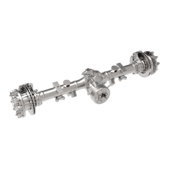
Differential Carriers
3000, 4000 and 5000 Series
Maintenance Manual MM-02133
Table of
Contents
Previous
Page
Next
Page
1
2
3
4
5
Advertisement
Table of Contents
Need help?
Do you have a question about the 3000 Series and is the answer not in the manual?
Ask a question
Questions and answers
Related Manuals for Meritor 3000 Series
Industrial Equipment Meritor Meritor ELSA 195 Maintenance Manual
Reaction beam air disc brake (49 pages)
Industrial Equipment Meritor PreSet Maintenance Manual
Hub assemblies for trailer axles, and steer and drive axles (25 pages)
Industrial Equipment Meritor MTC Series Maintenance Manual
One-piece transfer case (62 pages)
Industrial Equipment Meritor MM-0170 Maintenance Manual
(88 pages)
Industrial Equipment Meritor MTC-4208X Series Service Manual
Transfer cases (120 pages)
Industrial Equipment Meritor MORH2P035 Series Quick Start Manual
(4 pages)
Industrial Equipment Meritor MM-0861 Maintenance Manual
(118 pages)
Industrial Equipment Meritor 17X Maintenance Manual
Single reduction differential carrier (76 pages)
Industrial Equipment Meritor 13Х Series Maintenance Manual
Rear differential carrier (62 pages)
Industrial Equipment Meritor MM-2075 Maintenance Manual
(34 pages)
Industrial Equipment Meritor MM-96147 Maintenance Manual
Driveline (100 pages)
Industrial Equipment Meritor TM Series Service Manual
Trailer axle (56 pages)
Industrial Equipment Meritor LM Series Maintenance Manual
Trailer axle (61 pages)
Industrial Equipment Meritor RS-220 Maintenance Manual
Two-speed differentials (53 pages)
Industrial Equipment Meritor RS 120 Field Maintenance Manual
Single reduction axle (46 pages)
This manual is also suitable for:
4000 series
5000 series
Table of Contents
Print
Rename the bookmark
Delete bookmark?
Delete from my manuals?
Login
Sign In
OR
Sign in with Facebook
Sign in with Google
Upload manual
Upload from disk
Upload from URL


Need help?
Do you have a question about the 3000 Series and is the answer not in the manual?
Questions and answers