Advertisement
Table of Contents
- 1 Input Impedance
- 2 Output Impedance
- 3 Input Jacks
- 4 Gain Control
- 5 Aural Enhancer
- 6 Bass Control
- 7 Speaker On/Off Switch
- 8 Power On/Off Switch
- 9 Effects Section
- 10 Tuner out
- 11 Internal Features
- 12 Rack Mounting Instructions
- 13 Limited Warranty
- 14 Important Safety Instructions
- Download this manual
See also:
Owner's Manual
Advertisement
Table of Contents

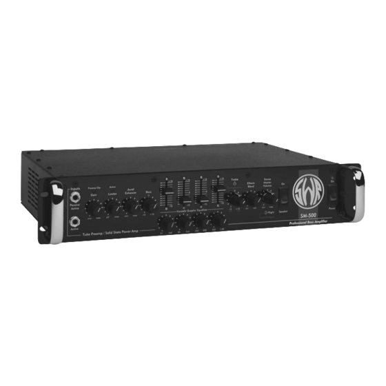
Summary of Contents for SWR SM-500
- Page 1 SM-500 USER GUIDE SWR SOUND CORP. • SUN VALLEY, CA • USA...
- Page 2 The tube employed in the preamp section of the SM-500 is a specially selected 12AX7 and should not require replacement for one to three years. To get the most out of your SM-500, please take the time to read through the entire owner’s manual. SM-500 USER GUIDE • 1...
- Page 3 Left and Right Stereo Output ® • One Speakon output jack for Mono/Bridge operation • (2) Speaker fuses: 3AG, 8 amp, fast-blo • (1) Line Fuse: 3AG, 7 amp, slo-blo • AC power cord receptacle 2 • SM-500 USER GUIDE...
-
Page 4: Input Impedance
SIGNAL TO NOISE RATIO: –72 dB (<10 millivolts typical) EQUIVALENT INPUT NOISE: 9 microvolts SIZE (measured from the rack ears back): 19" W x 3.5" H x 13.375" D (82.6 x 8.9 x 39.73 mm) WEIGHT: 20 lbs. (9.07 kg) SM-500 USER GUIDE • 3... -
Page 5: Input Jacks
1 volt RMS. Basses with really “hot” pickups may be more compatible with this input. If you are using a KEYBOARD or BASS PEDAL, etc. with the SM-500, we have found the best choice to be the Active input. -
Page 6: Aural Enhancer
Equalizer to +15 (the Frequency control should be set at 40Hz, which is the fundamental that the open “E” string produces). The change in sound and pressure levels is a result of the fundamental “E” note being increased by approximately 15db. SM-500 USER GUIDE • 5... -
Page 7: Speaker On/Off Switch
Stereo Master Volume control is a dual-concentric knob that offers individual volume control over both the right side (outer knob) and left side (inner knob) when the SM-500 is being run in the Stereo Mode. When the SM-500 is being run in the Bridge/Mono Mode, the inner knob controls the overall volume (the outer knob is disabled and will have no effect in Bridge/Mono Mode). -
Page 8: Power On/Off Switch
SM-500 REAR PANEL FEATURES AC CORD RECEPTACLE The SM-500 accepts a standard AC power cable (supplied with the SM-500), used with almost all cur- rent musical, professional and household electronic devices. If it becomes misplaced, a replacement can be purchased at almost any computer, electronics, or pro audio store. - Page 9 There are two 1/4" jacks and one Speakon SM-500. The Left and Right speaker jacks are provided for use in the Stereo Mode only. DO NOT use these jacks when the SM-500’s Power Amp Assign switch is in the “Bridge” position. You can bal- ance the Left and Right channels by using the Stereo Master Volume control located on the front panel.
-
Page 10: Effects Section
If you wish to use just the internal power amps in the SM-500, the Effects Return jacks will serve as the “inputs.” Insert your MONO signal source in the mono Effects Return jack. This will send the source to both power amps. -
Page 11: Internal Features
40 degrees centigrade. This greatly reduces component fatigue and increases reliability. For proper ventilation, make sure that all of the SM-500’s vents are unobstructed when installing it in a rack case. Note: At low volume levels, the cooling fan in the SM-500 may be audible. -
Page 12: Rack Mounting Instructions
The SM-500 takes up two full rack spaces (3 1/2"). If the rack in which you mount the SM-500 requires that the rubber feet on the bottom of the chassis be removed, please remember to REPLACE the screws, as they help to reinforce the chassis. - Page 13 You should be aware of the possibility of the power amp in your SM-500 becoming “over biased.” This condition can be recognized by turning your amplifier on and letting it sit without speakers plugged in and without playing it.
- Page 14 SM-500 USER GUIDE • 13...
- Page 15 14 • SM-500 USER GUIDE...
-
Page 17: Limited Warranty
Ship the unit PREPAID to the SWR Authorized Service Center of your choice. SWR Sound Corporation will provide free repair (parts and labor), or replacement at our option, on units determined to be under warranty. -
Page 18: Important Safety Instructions
IMPORTANT SAFETY INSTRUCTIONS CAUTION: TO REDUCE RISK OF ELECTRIC SHOCK, DO NOT REMOVE THE COVER OR BACK. NO USER-SERVICEABLE PARTS INSIDE. PLEASE REFER TO A QUALIFIED SERVICE TECHNICIAN. A. Read Instructions: All safety and operation instructions should be read before the product is operated. B. - Page 19 © 2001 SWR Sound Corp. All rights reserved. REV. 08/01 Part # 320027 Learn more about SWR products and artists by pointing your browser to: swrsound.com SWR SOUND CORPORATION 9130 Glenoaks Blvd. • Sun Valley, CA 91352 USA Phone: (818) 253-4797 • Fax: (818) 253-4799...


Need help?
Do you have a question about the SM-500 and is the answer not in the manual?
Questions and answers
Makes a crackling and popping noise when I start playing through it.