Table of Contents
Advertisement
SERVICE MANUAL
Fender Musical Instruments Corporation / 8860 East Chaparral Road, Suite 100 / Scottsdale, AZ 85250
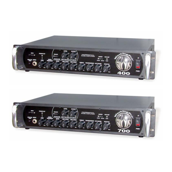
WorkingPro™ 400 & 700
(This is the model name for warranty claims)
Revised: January 2006
WorkingPro 700 p/n 4450000010 (120V)
WorkingPro 400 p/n 4450200010 (120V)
CONTENTS:
Notices ........................................... 2
Specifications ................................. 3
Service Notes................................. 4
Circuit Description.......................... 5
Main PCB Assembly................ 7
I/O PCB Assembly................... 9
Spkr Out PCB Assembly ....... 10
Pwr Supply PCB Assembly ... 10
Pwr Amp PCB Assembly....... 10
Power Module Assembly....... 12
Chassis Assembly ................. 13
Footswitch Assembly............. 14
Service Diagram List ................... 15
Advertisement
Table of Contents

Subscribe to Our Youtube Channel
Related Manuals for SWR WorkingPro 400


Summary of Contents for SWR WorkingPro 400
-
Page 1: Table Of Contents
WorkingPro™ 400 & 700 (This is the model name for warranty claims) WorkingPro 700 p/n 4450000010 (120V) WorkingPro 400 p/n 4450200010 (120V) SERVICE MANUAL CONTENTS: Notices ........... 2 Specifications ......... 3 Service Notes......... 4 Circuit Description......5 Parts Lists: Main PCB Assembly....7 I/O PCB Assembly.... -
Page 2: Notices
WorkingPro™ 400 & 700 (This is the model name for warranty claims) IMPORTANT NOTICE • Copyright © 2005 FMIC. All rights reserved. All specifications are subject to change without no- tice. This information and any copies produced information contained herein is CONFIDENTIAL electronically or otherwise must be surrendered and PROPRIETARY and is the property of upon demand of Fender®... -
Page 3: Specifications
WorkingPro™ 400 & 700 (This is the model name for warranty claims) SPECIFICATIONS MODEL: WorkingPro™ 400 WorkingPro™ 700 PART NUMBERS: 4450200010 (120V, 60Hz) USA 4450000010 (120V, 60Hz) USA POWER REQUIREMENT: 840 W 1440 W POWER AMP MINIMUM IMPEDANCE: 4Ω 4Ω SENSITIVITY: 700mV RMS, 1kHz 1V RMS, 1kHz... -
Page 4: Service Notes
WorkingPro™ 400 & 700 (This is the model name for warranty claims) SERVICE NOTES 1. TOP COVER REMOVAL is accomplished by jack. Disconnect the two ribbon cables at the PCB headers. removing 10 flat-head screws from the top & sides of the chassis. Then remove 4 hex cap 4. -
Page 5: Circuit Description
& is designed to deliver the same tone "EFF_RETURN_R" signal is grounded, so the and performance as the rest of the SWR amplifier Effects Blend control wiper is grounded. As the line. New electronic features to SWR include the... - Page 6 Headphone, Effects Send, & Effects Return. The WorkingPro 400. The SWR1000 module is used in other signals are for power & control. the WorkingPro 700. The Tuner Out comes from the "Direct" signal, and The power module receives its high voltage power is not affected by the tuner mute.
-
Page 7: Parts Lists
WorkingPro™ 400 & 700 (This is the model name for warranty claims) PARTS LIST: MAIN – PCB ASSEMBLY (Rev C) QTY. PART # DESCRIPTION REFERENCE DESIGNATION 006474600x PCB ASSY WORKINGPRO PREAMP SVC DIA COMB WORKINGPRO AMPS 0028474003 CAP AE RDL 100uF 25V 20% 0028463003 CAP AE RDL 10uF 50V 20% C5 C35... - Page 8 WorkingPro™ 400 & 700 (This is the model name for warranty claims) PARTS LIST: MAIN – PCB ASSEMBLY (Rev C) QTY. PART # DESCRIPTION REFERENCE DESIGNATION 0024981001 RES CF 1/4W 5% 10k LL R7-8 R10-11 R15 R27 R29 R33 R35 R39-40 R49 R52-53 R61 R63 R86-87 R94 R103 R121 R124-125 0024937001 RES CF 1/4W 5% 10ohm LL...
-
Page 9: I/O Pcb Assembly
WorkingPro™ 400 & 700 (This is the model name for warranty claims) PARTS LIST: I/O REAR PANEL – PCB ASSEMBLY (Rev B) QTY. PART # DESCRIPTION REFERENCE DESIGNATION 006474900x PCB ASSY WORKINGPRO I/O 0064747000 SVC DIA COMB. WORKINGPRO AMPS 0028467003 CAP AE RDL 22uF 50V 20% C204 0047195003... -
Page 10: Spkr Out Pcb Assembly
(Rev D) QTY. PART # DESCRIPTION REFERENCE DESIGNATION 0064548000 PCB ASSY SWR500/1000 PWR AMP SVC DIA COMB SWR 500/1000 PWR AMP 0038692000 CAP AE AX 10uF 35V 20% 0068838000 CAP AE RDL 2200uF 35V LP 105C C17-18 C29 0028458003 CAP AE RDL 1uF 50V 20% 0028460003 CAP AE RDL 4.7uF 50V 20%... - Page 11 WorkingPro™ 400 & 700 (This is the model name for warranty claims) PARTS LIST:POWER AMP – PCB ASSEMBLY (Rev D) QTY. PART # DESCRIPTION REFERENCE DESIGNATION 0013562000 IC REGULATOR +15V MC7815CT 0013564000 IC REGULATOR -15V MC7915CT 0050849000 HEATSINK PCB LEVEL 576012U @ U1-2 0017974000 INSULATOR MICA TO-220...
-
Page 12: Power Module Assembly
0028760000 XSTR NPN 2SC4793/2SC3298B 0027638000 SCRW TF 4-40x 3/8 HWHS ZI .1" @ driver xstrs, tunnel, & thermistor Items Below are for SWR500 Power Module Assy #0064714000, used in WorkingPro 400 0054804000 XSTR NPN 2SC2922 MT-200 Q36-38 0054805000 XSTR PNP 2SA1216 MT-200... -
Page 13: Chassis Assembly
0068325000 SWITCH ROCKER SPST 16A EURO (230/240V models) WIRESET CHASSIS WORKINGPRO AMPS LABEL, NORDIC (230/240V models) Items Below are for WorkingPro 400 Chassis Assy 0064714000 MODULE ASSY SWR500 PWR AMP 0064821000 **XFMR SWR 400 W AMPS 120V 60Hz (120V models) -
Page 14: Footswitch Assembly
Service Diagram (Schematic) ....WorkingPro Amplifiers Service Diagram (PCB Assembly) ....WorkingPro Amplifiers Service Diagram (Schematic) ....SWR 500/1000 Power Amp Service Diagram (PCB Assembly) ....SWR 500/1000 Power Amp * Non-serviceable part. Replace complete parent assembly. See PCB EXCHANGE POLICY above. shaded Unique Fender® part. Order directly from the FMIC Parts Department.
Need help?
Do you have a question about the WorkingPro 400 and is the answer not in the manual?
Questions and answers