Tescom i-com Series Installation And User Manual
External ups - modbus (tcp/ip) communication adapter
Hide thumbs
Also See for i-com Series:
- Installation and user manual (14 pages) ,
- User manual (19 pages) ,
- Installation and user manual (19 pages)

Subscribe to Our Youtube Channel
Related Manuals for Tescom i-com Series


Summary of Contents for Tescom i-com Series
- Page 1 SERIES EXTERNAL UPS – MODBUS (TCP/IP) COMMUNICATION ADAPTER (MDX-NET) INSTALLATION AND USER MANUAL - 1 -...
-
Page 3: Table Of Contents
Thank you for selecting our product to protect your electrical equipment. The Modbus adaptor has been designed with the utmost care. We recommend that you take the time to read this manual to take full advantage of the many features of your new equipment. Environment Our staff pays great attention to the environmental impact of its products during the design and manufacture stages, through to the end of its life cycle. - Page 4 - 1 -...
-
Page 5: Introduction
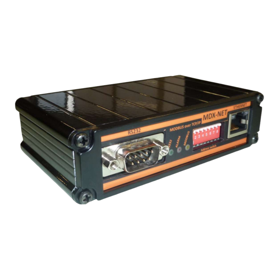
1. Introduction 1.1 Unpacking and Checking Contents EXTERNAL MODBUS ADAPTOR 5 volts DC power supply RS232 UPS-ADAPTOR cable (CC05) Utility CD Installation and user manual 1.2 Overview 1.3 Functions The MODBUS TCPIP communication adaptor provides UPS (Uninterruptible Power supply) data (states and measures) to be sent a computer system. -
Page 6: Installation
2. Installation 2.1 Configuration Of The Modbus Communication Parameters The device takes the device number during power on please select device number from 1 to 255 by setting device number dip switches Where D is the n dip switch. For example, if we need to set the device’s address to 183 then we need to set 7 , and 0 dip switch pins. -
Page 7: Rs232 Connection To Ups
2.2 RS232 Connection to UPS Connect CC05 RS232 cable from serial port connector of the MODBUS adapter to the serial port of the UPS. CC05 RS232 Data Cable Max. Length = 25 meters. parts 9 pins D type connector (male) 9 pins D type connector(female) 3 wired shielded cable Max 25 meters... -
Page 8: Installation
2.4 Installation Check RS232 UPS connection ,check ethernet connection if connections are OKAY Connect the power cord of the MODBUS TCPIP adapter to mains power (The power of the adapter must be supplied from UPS output otherwise during line failure the power of the MODBUS adapter shutdown) 2.5 MDX-NET Configuration using Device Installer Run device installer software. - Page 9 At “Assign IP” window select *Static IP* option from configuration window and click on *NEXT* button. NOTE : The new IP address is different from 10.0.0.xxx or subnet mask is different from 255.0.0.0 value the adaptor connection may be lost in this case please re adjust your PC network settings to these network values. - 5 -...
- Page 10 After adjust MDX-NET IP addresses the new assigned IP address will be showned at device installer program window. For detailed configuration we must connect to adaptor as WEB page to do this from device installer program click on WEB configuration. Than click on *GO* button and device main WEB PAGE comes to screen. Ignore username and password values for the first time.
- Page 11 For MDX-NET serial port configuration at the left side menu click on *Serial settings* serial configuration page comes to screen. Parameter value Baud rate 9600 Enable packing checked Click on *OK* button for update settings at the end of page For MDX-NET Ethernet configuration from the left side manu click on *Connection* related configuration page comes to screen.
-
Page 12: Operation
3. Operation Turn on the UPS During power up the MODBUS adaptor will check the UPS communication version if it supports the version it will run. The MDX2 MODBUS adaptor supports TX100, TX300 and TX301 UPS communication protocols. For Test Purpose download MODBUS tester program from the link http://www.modbus.pl/modbus.htm 4. -
Page 13: Tx300 Protocol Holding Register Table (3 Phase Ups)
TX300 PROTOCOL HOLDING REGISTER map (for 3 phase UPS) MEASUREMENT GROUP (TX300 PROTOCOL) Addr Parameter Unit Min-max PROTOCOL 0-511 RECTIFIER INPUT VOLTAGE 1 phase-neutral ( * ) 0-511 RECTIFIER INPUT VOLTAGE 2 phase-neutral ( * ) 0-511 RECTIFIER INPUT VOLTAGE 3 phase-neutral ( * ) Not used Not used Not used... - Page 14 ALARM AND STATUS GROUP BIT MEANING (TX300 PROTOCOL) Addr Alarms Description inverter heatsink overtemp ( >85 7(128) 1=ALARM 0=NORMAL inverter output voltage high ( >242V ) 6(64) 1=ALARM 0=NORMAL inverter output voltage low ( <170V ) 5(32) 1=ALARM 0=NORMAL output overload (>%150) 4(16) 1=ALARM 0=NORMAL...
-
Page 15: Tx301 Protocol Holding Register Table (3 Phase Ups)
TX301 PROTOCOL HOLDING REGISTER map (for 3 phase UPS) MEASUREMENT GROUP (TX301 PROTOCOL) Addr Parameter Unit Min-max PROTOCOL Rectifier module status codes 0-999 Inverter module status codes 0-999 Not used Not used Not used Not used Not used Not used INPUT VOLTAGE 1 phase-neutral 0-511 0-512... - Page 16 INPUT CURRENT PHASE 1 (if option board is used) 0-511 INPUT CURRENT PHASE 2 (if option board is used) 0-511 0-511 INPUT CURRENT PHASE 3 (if option board is used) Not used Not used Not used Not used Not used Not used % LOAD 0-255...
- Page 17 ALARM AND STATUS GROUP BIT MEANING (TX301 PROTOCOL) Addr Alarms Description İnverter IGBT ALARM 0 (1) 1=ALARM 0=NORMAL Overtemperature 1 (2) 1=ALARM 0=NORMAL Battery volt high 2 (4) 1=ALARM 0=NORMAL İnverter AC LOW 3 (8) 1=ALARM 0=NORMAL İnverter AC HIGH 4 (16) 1=ALARM 0=NORMAL...
- Page 18 DC BUS voltage HIGH 2 (4) 1=ALARM 0=NORMAL DC BUS voltage LOW 3 (8) 1=ALARM 0=NORMAL Rectifier input frequency BAD 4 (16) 1=ALARM 0=NORMAL Overtemperature warning 5 (32) 1=ALARM 0=NORMAL Blackout 6 (64) 1=ALARM 0=NORMAL Rectifier IGBT alarm 7 (128) 1=ALARM 0=NORMAL Rotate rectifier input phases...
-
Page 19: Tx100 Protocol Holding Register Table (3 Phase Ups)
TX100 PROTOCOL HOLDING REGISTER map (for 1 phase UPS) MEASUREMENT GROUP (TX100 PROTOCOL) Addr Parameter Unit Min-max PROTOCOL 0-511 RECTIFIER INPUT VOLTAGE 1 phase-phase 0-511 RECTIFIER INPUT VOLTAGE 2 phase-phase 0-511 RECTIFIER INPUT VOLTAGE 3 phase-phase Not used Not used Not used Not used BYPASS INPUT VOLTAGE 1 phase-phase... - Page 20 ALARM AND STATUS GROUP BIT MEANING (TX100 PROTOCOL) Addr Alarms Description inverter heatsink overtemp 7(128) 1=ALARM 0=NORMAL inverter output voltage high 6(64) 1=ALARM 0=NORMAL inverter output voltage low 5(32) 1=ALARM 0=NORMAL output overload 4(16) 1=ALARM 0=NORMAL battery voltage high 3(8) 1=ALARM 0=NORMAL internal overcurrent...
-
Page 21: Sts Protocol Holding Register Table (Static Transfer Switch)
STS PROTOCOL HOLDING REGISTER map (for STATIK TRANSFER SWITCH) MEASUREMENT GROUP (STS PROTOCOL) Addr Unit Min-max Parameter PROTOCOL SOURCE-1 INPUT VOLTAGE Phase-Neutral (L1) 0-511 SOURCE-1 INPUT VOLTAGE Phase-Neutral (L2) 0-511 SOURCE-1 INPUT VOLTAGE Phase-Neutral (L3) 0-511 SOURCE-2 INPUT VOLTAGE Phase-Neutral (L1) 0-511 SOURCE-2 INPUT VOLTAGE Phase-Neutral (L2) 0-511... - Page 22 ALARM AND STATUS GROUP BIT MEANING (STS PROTOCOL) Addr Alarms Description Source-1 Voltage out of tolerant 7(128) 1=ALARM 0=NORMAL Source-1 phase synchron not OK 6(64) 1=ALARM 0=NORMAL Not used 5(32) Source-1 Black Out 4(16) 1=ALARM 0=NORMAL Source-1 Balance bad 3(8) 1=ALARM 0=NORMAL Source-1 Frequency bad...
- Page 23 - 19 -...
Need help?
Do you have a question about the i-com Series and is the answer not in the manual?
Questions and answers