Table of Contents
Advertisement
Quick Links
These instructions apply only to the destination countries listed on the appliance's data
plate.
This is a class 3 built-in hob.
We advise you to read this manual carefully, as it contains all the instructions for maintaining
the appliance's aesthetic and functional qualities.
For further information on the product: www.smeg.com
Contents
40
40
44
44
44
44
45
46
47
47
48
49
49
50
50
50
50
51
55
55
55
57
57
57
59
60
61
63
72
73
39
Advertisement
Table of Contents

Related Manuals for Smeg S64SN


Summary of Contents for Smeg S64SN
-
Page 1: Table Of Contents
These instructions apply only to the destination countries listed on the appliance's data plate. This is a class 3 built-in hob. We advise you to read this manual carefully, as it contains all the instructions for maintaining the appliance’s aesthetic and functional qualities. For further information on the product: www.smeg.com... -
Page 2: Instructions
Instructions 1 Instructions • Fats and oils can catch fire if they overheat. Do not leave the 1.1 General safety instructions appliance unattended while preparing foods containing oils or Risk of personal injury fats. If fats or oils catch fire, never •... - Page 3 Instructions • Do not modify this appliance. • Do not try to repair the appliance yourself or without the intervention • Do not insert pointed metal of a qualified technician. objects (cutlery or utensils) into the slots in the appliance. •...
- Page 4 Instructions Risk of damaging the appliance • Do not put empty pans or frying pans on switched on cooking • Do not sit on the appliance. zones. • Do not use steam jets to clean the • Do not use rough or abrasive appliance.
- Page 5 Instructions • Position the appliance into the • If required, use a pressure cabinet cut-out with the help of a regulator that complies with second person. current regulations. • To prevent any possible • After carrying out any operation, overheating, the appliance should check that the tightening torque of not be installed behind a gas connections is between...
-
Page 6: Manufacturer Liability
Instructions • This domestic appliance is not 1.3 Appliance purpose connected to a device for This appliance is intended for extracting combustion products. It cooking food in the home must be installed and connected environment. Every other use is in accordance with current considered inappropriate. -
Page 7: Disposal
Instructions 1.6 Disposal • Cut the power supply cable and remove it along with the plug. This appliance must be • Deliver the appliance to the disposed of separately from appropriate recycling centre for other waste (Directives electrical and electronic 2002/95/EC, equipment waste, or return it to the 2002/96/EC, 2003/108/EC). -
Page 8: How To Read The User Manual
Instructions 1.7 How to read the user manual This user manual uses the following reading conventions: Instructions General information on this user manual, on safety and final disposal. Description Description of the appliance and its accessories. Information on the use of the appliance and its accessories. -
Page 9: Description
Description 2 Description 2.1 General Description 60 cm... -
Page 10: Symbols
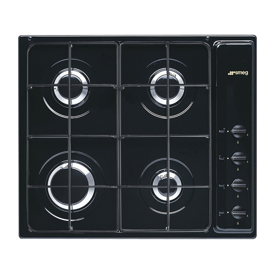
Description 90 cm 1 Control panel Cooking zones 2 Auxiliary burner (AUX) 3 Semi-rapid burner (SR) Rear right 4 Rapid burner (R) 5 Ultra-rapid burner (UR) 6 Electric hot plate Rear left 7 Fish kettle burner (FB) 8 Right grid Front right 9 Central grid 10 Left grid... -
Page 11: Burner Knobs
Description 2.3 Burner knobs 2.4 Available accessories Not all accessories are available on some models. Ring reducer Useful when using small cookware. To be used only on AUX (auxiliary) burner. Used for lighting and adjusting the hob The accessories intended to come burners. -
Page 12: Use
3 Use 3.2 First use 1. Remove any protective film from the 3.1 Instructions outside or inside of the appliance, including accessories. Improper use 2. Remove any labels (apart from the Danger of burns technical data plate) from accessories. 3. Remove and wash all the appliance's •... -
Page 13: Using The Hob
3.4 Using the hob Correct positioning of the grids The grids over the burners must be All the appliance's control and monitoring positioned in parallel to the control panel, devices are located together on the side not perpendicular. panel. The burner controlled by each knob is shown next to the knob. - Page 14 Correct positioning of the flame- Once the contents come to the boil, turn spreader crowns and burner caps down the flame far enough to ensure that the liquid does not boil over. Before lighting the hob burners, make sure that the flame-spreader crowns are Cookware diameters: correctly positioned in their seats with their •...
- Page 15 Limitations on griddle use Using the electric hot plate A few precautions are necessary if you wish Improper use to use a griddle: Risk of damage to the appliance • Griddles should be placed inside the perimeter of the hob and should not •...
- Page 16 Power When switching the plate on for Position Cooking type level the first time, or in cases where this has not been used for a long time, plate off heat it for 30 minutes at minimum for melting butter, power (without adding pans), to chocolate, etc.
-
Page 17: Cleaning And Maintenance
Cleaning and maintenance 4 Cleaning and maintenance 4.2 Cleaning the appliance To keep the surfaces in good condition, 4.1 Instructions they should be cleaned regularly after use. Let them cool first. Improper use Risk of damage to surfaces Ordinary daily cleaning Always use specific products only that do •... - Page 18 Cleaning and maintenance Cooking hob grids Igniters and thermocouples Remove the grids and clean them in For correct operation the igniters and lukewarm water and non-abrasive thermocouples must always be perfectly detergent. Make sure to remove any clean. Check them frequently and clean encrustations.
-
Page 19: Installation
Installation 5 Installation 5.2 Section cut from the countertop The following operation requires 5.1 Safety instructions building and/or carpentry work Heat production during appliance and must therefore be carried out operation by a competent tradesman. Risk of fire Installation can be carried out on various materials such as masonry, •... - Page 20 Installation Overall dimensions: gas and electrical 90 cm models: connection location (measures in mm) 60 cm models: View from the bottom G Gas connection E Electrical connection View from the bottom G Gas connection E Electrical connection Right view Right view Rear view Rear view...
-
Page 21: Mounting
Installation 5.3 Mounting Over empty kitchen unit or drawers If there are other pieces of furniture (lateral Over built-in oven unit walls, drawers, etc.), dishwashers or fridges The clearance between the hob and the under the hob, a double-layer wooden kitchen furniture or other installed base must be installed at least 10 mm from appliances must be enough to ensure... -
Page 22: Fixing To The Supporting Structure
Installation 5.4 Fixing to the supporting structure Hob seal Fix the hob to the unit using the appropriate To prevent leakage of liquid between the frame of the hob and the work surface, bracket (A) and the spacer (B) supplied. place the insulating seal provided in position before assembly, as shown in the figure below. -
Page 23: Gas Connection
Installation General information Connection to the gas mains can be made using a rigid copper pipe or a continuous wall steel hose in compliance with the provisions established by the applicable standard. For supplying it with other types of gas, see chapter “5.6 Adaptation to different types of gas”. - Page 24 Installation Connection with a steel hose with conical Room ventilation fitting This domestic appliance is not Make the connection to the gas mains connected to a device for using a continuous wall steel hose whose extracting combustion products. It specifications comply with the applicable must be installed and connected in standard.
-
Page 25: Adaptation To Different Types Of Gas
Installation When the job is complete, the installer must 5.6 Adaptation to different types of issue a certificate of conformity. If other types of gas are to be used, the nozzles must be replaced and the primary air must be adjusted. In order to replace the nozzles and adjust the burners, the hob top must be removed. - Page 26 Installation 6. Remove the front panel by lifting it Removing the hob top (models with integrated control panel) towards the right. 7. Remove all the burners from the hob. 8. Unscrew the screws under each burner to remove the fixing plate. 9.
- Page 27 Installation Replacing the nozzles/air regulation 3. Adjust the air flow by moving the Venturi tube ‘C’ to obtain the distance “A” given in the relevant table (see “Gas types and Countries”). 4. After adjusting each burner, reassemble the appliance correctly. Adjusting the minimum setting for natural or town gas Light the burner and turn it to the minimum...
- Page 28 Installation Adjusting the minimum setting for LPG Tighten the screw located at the side of the cock rod clockwise all the way. Following adjustment to a gas other than the one originally set in the factory, replace the gas setting label on the appliance with the one corresponding to the new gas.
- Page 29 Installation Gas types and Countries Gas types IT GB-IE FR-BE DE 1 Natural gas G20 20 mbar • • • • • • • • • • G20/25 20/25 mbar 2 Natural gas G20 25 mbar • 3 Natural gas G25.1 G25.1 25 mbar •...
- Page 30 Installation Burner and nozzle characteristics table (60 cm models) 1 Natural gas G20 - 20 mbar Rated heating capacity (kW) 1.10 1.80 3.10 4.10 Nozzle diameter (1/100 mm) Reduced flow rate (W) 1500 Primary air (mm) 2 Natural gas G20 - 25 mbar Rated heating capacity (kW) 1.10 1.80...
- Page 31 Installation 7 LPG G30/31 - 30/37 mbar Rated heating capacity (kW) 1.10 1.70 3.10 4.10 Nozzle diameter (1/100 mm) Reduced flow rate (W) 1500 Primary air (mm) open Rated flow rate G30 (g/h) Rated flow rate G31 (g/h) 8 LPG G30/31 - 37 mbar Rated heating capacity (kW) 1.10 1.80...
- Page 32 Installation Burner and nozzle characteristics table (90 cm models) 1 Natural gas G20 - 20 mbar Rated heating capacity (kW) 1.10 1.80 2.60 2.90 4.10 Nozzle diameter (1/100 mm) Reduced flow rate (W) 1500 Primary air (mm) 2 Natural gas G20 - 25 mbar Rated heating capacity (kW) 1.10 1.80...
- Page 33 Installation 7 LPG G30/31 - 30/37 mbar Rated heating capacity (kW) 1.10 1.70 2.60 2.90 4.10 Nozzle diameter (1/100 mm) Reduced flow rate (W) 1500 Primary air (mm) open Rated flow rate G30 (g/h) Rated flow rate G31 (g/h) 8 LPG G30/31 - 37 mbar Rated heating capacity (kW) 1.10 1.80...
-
Page 34: Electrical Connection
Installation 5.7 Electrical connection The appliance can work in the following modes: 220-240 V 1N~ Power voltage Danger of electrocution • Have the electrical connection performed by authorised technicians. Use a 3 x 1 mm² three-core cable. • Use personal protective equipment. The values indicated above refer •... -
Page 35: Instructions For The Installer
Installation 5.8 Instructions for the installer • The plug must be accessible after installation. Do not bend or trap the power cable. • The appliance must be installed according to the installation diagrams. • Do not try to unscrew or force the threaded elbow of the fitting.
Need help?
Do you have a question about the S64SN and is the answer not in the manual?
Questions and answers