Advertisement
Quick Links
Echoflex Installation Guide
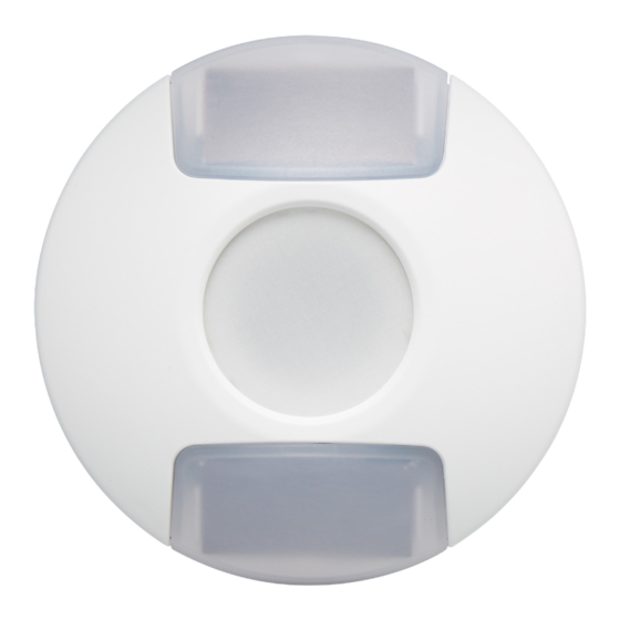
Photo & CCT Sensors TAP-31 TAP-41
Overview
The Photo Sensor (TAP-31) and CCT & Photo Sensor (TAP-41) are wireless
solar-powered sensors that provide a reliable and simple method for
increasing energy savings by adding daylight harvesting capability to an
Echoflex lighting control system.
The TAP-31 supports two equipment
profile settings that measure ambient light
intensity in two ranges: 0–1,020 lux
(0–95 fc) and 0–65,535 lux (0–6,090 fc).
The TAP-41 combines correlated color
temperature (CCT) and light intensity
monitoring to match fixture output with
outdoor values or predefined color
temperature values. The sensor supports
four equipment profile settings that
monitor exterior light levels up to
100,000 lux (9,290 fc) and a color
temperature range of 2,000–7,500 kelvin to maximize the lighting
adjustment for a tunable white LED fixture throughout the day.
This document covers installation, testing, and settings that apply to all
TAP-31 and TAP-41 models. The product package includes the sensor and
two wire staples.
Prepare for Installation
To ensure optimal function, consider the installation environment and the
following guidelines:
For indoor use only. Operating temperature -25°C to 65°C
•
(-13°F to 149°F), 5%–92% relative humidity (non-condensing).
High density construction materials and large metal appliances or
•
fixtures in the space may disrupt wireless transmissions.
Install the sensor within range of linked receivers or controllers,
•
24 m (80 ft) unobstructed view. Consider adding a repeater to
extend the wireless signal, if required.
Before linking the sensor, expose it to a good light source for at least
•
five minutes at 200 lux (19 fc).
Supplies required to install (not provided):
Two #6 screws, double-sided tape, or Velcro
•
Corporate Headquarters n Middleton, WI, USA | +1 608 831 4116
Web
echoflexsolutions.com
©2022 Echoflex Solutions, Inc. Trademark and patent
Product information and specifications subject to change.
Echoflex intends this document to be provided in its entirety.
8188M2107 Rev A Released 2022-05
| Email
info@echoflexsolutions.com
| Support
service@echoflexsolutions.com
info: echoflexsolutions.com/ip
®
Advertisement

Related Manuals for echoflex TAP-31


Summary of Contents for echoflex TAP-31
- Page 1 Echoflex Installation Guide Photo & CCT Sensors TAP-31 TAP-41 Overview The Photo Sensor (TAP-31) and CCT & Photo Sensor (TAP-41) are wireless solar-powered sensors that provide a reliable and simple method for increasing energy savings by adding daylight harvesting capability to an Echoflex lighting control system.
-
Page 2: Installation
The location and position of the sensor directly affects the quality of messages received by the linked controller. Determine the installation method and follow the instructions. Note: Consider linking the TAP-31 TAP-41 while you have access and before replacing the cover. See Link to a Controller on the facing page. -
Page 3: Battery Power
Link to a Controller The compatible target controller must be installed, powered, and within range of the TAP-31 TAP-41. Note: The linking process can be used both to link a device to a controller and to unlink a linked device from a controller. -
Page 4: Sensor Operation
Echoflex Installation Guide Photo & CCT Sensors Sensor Operation The sensor records sample values at a rate based on the current ambient light level and the stored energy in the sensor. The sensor is configured to transmit messages at a heartbeat rate and immediately when daylight levels change more than 12%. -
Page 5: Light Level Test
Echoflex Installation Guide Photo & CCT Sensors Tests and Settings Use the [Teach] button and color LEDs to navigate the Tests and Settings menu. Remove the cover to access the [Teach] button located beside the battery clip. The LEDs display through the front lens. - Page 6 Note: Only one controller can be linked to the TAP-31 TAP-41 to run the test properly. Disable repeaters that are in range. 1. Press and hold the [Teach] button until the green LED is displayed.
- Page 7 Echoflex Installation Guide Photo & CCT Sensors EEP Select The default EEP setting is configured to work with Echoflex controllers. You can configure the sensor to be compatible with controllers that use an alternate profile. 1. Press and hold the [Teach] button until the green LED is displayed.
- Page 8 Photo & CCT Sensors Compliance For complete regulatory compliance information, see the datasheets for the Photo & CCT Sensors at echoflexsolutions.com. FCC Compliance Echoflex Photo & CCT Sensors (For any FCC matters): Echoflex Solutions, Inc. 3031 Pleasant View Road Middleton, WI 53562 +1 (608) 831-4116 echoflexsolutions.com...