Table of Contents
Advertisement
Quick Links
echoflex
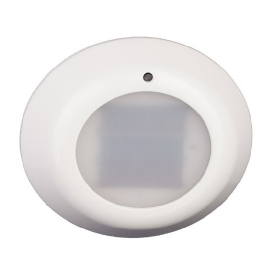
Task Ambient Photo Sensor
Overview
This guide covers all models of TAP-21 sensor.
The TAP-21 product family includes:
• TAP-21U Photo Sensor with 902 MHz radio
• TAP-21C Photo Sensor with 315 MHz radio
• TAP-21Y Photo Sensor with 868 MHz radio
• TAP-21J Photo Sensor with 928 MHz radio
The package includes the photo sensor and installation guide.
TAP-21 Sensor Description
The 21 series TAP Task Ambient Photo sensor (also referred to as the sensor
in this guide) is a wireless, energy harvesting sensor that monitors light levels
within interior spaces and transmits the value to lighting controllers.
The sensor measures ambient light in two ranges: 0-510 lux (0 - 50 foot candles)
and 0-1024 lux (0 - 100 fc) and is intended for indoor use only.
NOTE: The TAP is a solar powered device that absorbs solar energy storing it for use
during low light periods. Before assigning the TAP device to a receiver/controller, the
device should be exposed to a good light source for a minimum of 5 minutes or install a
start assist battery.
Installation Guide
TAP-21
Advertisement
Table of Contents

Related Manuals for echoflex TAP-21C


Summary of Contents for echoflex TAP-21C
- Page 1 This guide covers all models of TAP-21 sensor. The TAP-21 product family includes: • TAP-21U Photo Sensor with 902 MHz radio • TAP-21C Photo Sensor with 315 MHz radio • TAP-21Y Photo Sensor with 868 MHz radio • TAP-21J Photo Sensor with 928 MHz radio The package includes the photo sensor and installation guide.
- Page 2 Page Left Blank Intentionally...
- Page 3 Sensor Operation The Task Ambient Photo (TAP) sensor monitors interior light levels. The TAP sensor is powered by solar energy from natural or artificial light sources. The solar energy is transformed into electrical energy which is then stored, providing a continuous power source for the sensor. The sensor will operate even with a brief exposure to light, however for best results the sensor should be mounted in a location with exposure of 3-6 hours of natural or artificial light (250 - 500 lux or 25-50 fc) on a daily basis.
- Page 4 The sensor must be installed in the space where the receiving lighting controller is operating the light fixtures. See the sections on light level test and range confirmation* to aid in optimal placement. * -(requires F series Echoflex controller) The sensor can be mounted using screws (not supplied) through the back plate or using double-sided tape or Velcro™...
- Page 5 Note: • Range Confirmation only available with “F series” Echoflex Controllers. • The TAP must be at full charge and/or have the battery installed for Range Confirmation Tests energy requirements.
- Page 6 the LED indicators. When the amber LED is blinking, go to step 3. 3. Press and hold the test button again for 6 seconds to select Range Confirmation Test. All three LED’s will blink on and off (for 1 second) in this test mode, then if the sensor receives a range confirmation telegram, the sensor displays the linked signal strength status for 2.5 seconds, see table below.
- Page 7 Installing Wireless Devices Careful planning is needed when locating the receivers and transmitters based on the construction materials in the space and possibility of tenant’s furniture disrupting the transmissions. The sensor should be installed in the space where the receiver is mounted. The signal will travel through some material barriers.
- Page 8 Construction Type Conformity Certificate (928 MHz model only) TCM 410J complies with the Japanese radio law and is certified according to ARIB STDT108. Copyright 2013-2015 Echoflex Solutions, Inc. | Specifications subject to change without notice. Document #8DC-5365 | Revision 1.5 | 8188M21-5365-1 | Rev C Echoflex Solutions, Inc.
Need help?
Do you have a question about the TAP-21C and is the answer not in the manual?
Questions and answers