Table of Contents
Advertisement
Quick Links
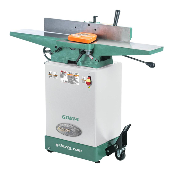
MODEL G0814/G0814X
6" JOINTER w/STAND
OWNER'S MANUAL
(For models manufactured since 04/22)
COPYRIGHT © MARCH, 2016 BY GRIZZLY INDUSTRIAL, INC., REVISED JUNE, 2022 (CS)
WARNING: NO PORTION OF THIS MANUAL MAY BE REPRODUCED IN ANY SHAPE
OR FORM WITHOUT THE WRITTEN APPROVAL OF GRIZZLY INDUSTRIAL, INC.
#BL18046 PRINTED IN TAIWAN
V3.06.22
***Keep for Future Reference***
Advertisement
Table of Contents

Related Manuals for Grizzly G0814


Summary of Contents for Grizzly G0814
- Page 1 OWNER'S MANUAL (For models manufactured since 04/22) COPYRIGHT © MARCH, 2016 BY GRIZZLY INDUSTRIAL, INC., REVISED JUNE, 2022 (CS) WARNING: NO PORTION OF THIS MANUAL MAY BE REPRODUCED IN ANY SHAPE OR FORM WITHOUT THE WRITTEN APPROVAL OF GRIZZLY INDUSTRIAL, INC.
- Page 2 This manual provides critical safety instructions on the proper setup, operation, maintenance, and service of this machine/tool. Save this document, refer to it often, and use it to instruct other operators. Failure to read, understand and follow the instructions in this manual may result in fire or serious personal injury—including amputation, electrocution, or death.
-
Page 3: Table Of Contents
Cleaning & Protecting ........37 Identification ........... 3 Lubrication ........... 38 Controls & Components ......... 4 G0814 Machine Data Sheet ......6 SECTION 7: SERVICE ........39 G0814X Machine Data Sheet ......8 Troubleshooting ........... 39 Setting/Replacing Knives (G0814) ....41 SECTION 1: SAFETY ........ -
Page 4: Introduction
Machine Differences tech support, and it helps us determine if updated documentation is available for your machine. Models G0814 and G0814X are 1 HP, 6" jointers with the following difference: Model G0814 has a 3-knife cutterhead. •... -
Page 5: Identification
Always use hold-down or push blocks when jointing material narrower than 3" or surface planing material thinner than 3". e) Never perform jointing, planing, or rabbeting cuts on pieces shorter than 8" in length. Model G0814/G0814X (Mfd. Since 04/22) -
Page 6: Controls & Components
G. Outfeed Table: Supports workpiece after key to disable switch. it passes over cutterhead. For safety and best results, outfeed table must be properly adjusted relative to cutterhead knives/inserts before ANY operations (refer to Page 44 for more details). Model G0814/G0814X (Mfd. Since 04/22) - Page 7 O. Fence Lock: Loosens to allow adjustment of fence position along width of tables. Tightens to secure fence. P. Swing Stop: When engaged, stops fence at 90°. When disengaged, allows fence to adjust for bevel cuts. Model G0814/G0814X (Mfd. Since 04/22)
-
Page 8: G0814 Machine Data Sheet
MACHINE DATA SHEET Customer Service #: (570) 546-9663 · To Order Call: (800) 523-4777 · Fax #: (800) 438-5901 MODEL G0814 6" X 48" JOINTER WITH CABINET STAND Product Dimensions: Weight................................245 lbs. Width (side-to-side) x Depth (front-to-back) x Height..............47-1/2 x 20 x 42 in. - Page 9 The information contained herein is deemed accurate as of 6/12/2022 and represents our most recent product specifications. Model G0814 PAGE 2 OF 3 Due to our ongoing improvement efforts, this information may not accurately describe items previously purchased. Model G0814/G0814X (Mfd. Since 04/22)
-
Page 10: G0814X Machine Data Sheet
The information contained herein is deemed accurate as of 5/17/2022 and represents our most recent product specifications. Model G0814X PAGE 1 OF 3 Due to our ongoing improvement efforts, this information may not accurately describe items previously purchased. Model G0814/G0814X (Mfd. Since 04/22) - Page 11 The information contained herein is deemed accurate as of 5/17/2022 and represents our most recent product specifications. Model G0814X PAGE 2 OF 3 Due to our ongoing improvement efforts, this information may not accurately describe items previously purchased. Model G0814/G0814X (Mfd. Since 04/22)
-
Page 12: Section 1: Safety
Never operate under the influence of drugs or injury or blindness from flying particles. Everyday alcohol, when tired, or when distracted. eyeglasses are NOT approved safety glasses. -10- Model G0814/G0814X (Mfd. Since 04/22) - Page 13 Make sure they are properly installed, you experience difficulties performing the intend- undamaged, and working correctly BEFORE ed operation, stop using the machine! Contact our operating machine. Technical Support at (570) 546-9663. -11- Model G0814/G0814X (Mfd. Since 04/22)
-
Page 14: Additional Safety For Jointers
Straight knives should never project MAXIMUM CUTTING DEPTH. To reduce risk of more than ⁄ " (0.125") from cutterhead body. kickback, never cut deeper than ⁄ " per pass. -12- Model G0814/G0814X (Mfd. Since 04/22) -
Page 15: Section 2: Power Supply
Nominal Voltage ..208V, 220V, 230V, 240V meets the specified circuit requirements. Cycle ............60 Hz Phase ........... Single-Phase Power Supply Circuit ......15 Amps Plug/Receptacle ......NEMA 6-15 -13- Model G0814/G0814X (Mfd. Since 04/22) - Page 16 The plug must only be inserted into a matching receptacle (see following figure) that is properly installed and grounded in accordance with all local codes and ordinances. -14- Model G0814/G0814X (Mfd. Since 04/22)
-
Page 17: Voltage Conversion To 220V
Open motor junction box, remove (2) wire nuts indicated in Figure 7, then disconnect wires. To Switch Remove Wire Nuts and Disconnect Wires Ground Figure 7. Inside motor junction box (motor pre- wired to 110V). -15- Model G0814/G0814X (Mfd. Since 04/22) -
Page 18: Section 3: Setup
No list of safety guidelines can be com- you are completely satisfied with the machine and plete. Every shop environment is different. have resolved any issues between Grizzly or the Always consider safety first, as it applies shipping agent. You MUST have the original pack- to your individual working conditions. -
Page 19: Inventory
C. Cutterhead Guard ........1 D. Belt Guard ..........2 E. Knife-Setting Jig (G0814) ......1 Push Blocks ..........2 G. Hex Wrench 3mm (G0814) ......1 H. Belt ............. 1 Fence Lock w/Locking Nut ......1 Fence Tilt Lever .......... 1 K. -
Page 20: Hardware Recognition Chart
Hardware Recognition Chart USE THIS CHART TO MATCH UP HARDWARE DURING THE INVENTORY AND ASSEMBLY PROCESS. Flat Head Screw -18- Model G0814/G0814X (Mfd. Since 04/22) -
Page 21: Cleanup
Figure 10. T23692 Orange Power Degreaser. Repeat Steps 2–3 as necessary until clean, then coat all unpainted surfaces with a quality metal protectant to prevent rust. -19- Model G0814/G0814X (Mfd. Since 04/22) -
Page 22: Site Considerations
Only install in an Shadows, glare, or strobe effects that may distract access restricted location. or impede the operator must be eliminated. Wall Min. 30" for Maintenance " 20" = Electrical Connection Figure 11. Minimum working clearances. -20- Model G0814/G0814X (Mfd. Since 04/22) -
Page 23: Assembly
Place stand in upright position and adjust lev- Motor eling feet as needed with hex nuts so stand Pulley rests level and stable on floor. Remove rear panel to access mounting holes Figure 15. Pulley alignment. in stand during next step. -21- Model G0814/G0814X (Mfd. Since 04/22) - Page 24 Fence Carriage Carriage Belt Support Base Bottom View Fence Locking Figure 18. Example of belt installed onto Figure 20. Fence assembly installed onto cutterhead and motor pulleys. carriage base and secured with fence lock. -22- Model G0814/G0814X (Mfd. Since 04/22)
- Page 25 Handwheel cutterhead guard shaft. Cutterhead guard must always return to closed position whenever it is moved. If it does not do this, it must be re-adjusted or re-installed. Figure 23. Outfeed table handwheel installed. -23- Model G0814/G0814X (Mfd. Since 04/22)
-
Page 26: Dust Collection
Figure 25. Belt guard and dust port installed. Fit 4" dust hose over dust port, as shown in Figure 27, and secure with a hose clamp. 21. G0814 Only: Assemble knife-setting gauge, as shown in Figure 26. Figure 26. Knife-setting gauge assembled. -
Page 27: Test Run
The motor should run smoothly and without Knife/Insert Settings (Pages 41 & 43). unusual problems or noises. Depth Scale Calibration (Page 45). Remove switch disabling key, as shown in Figure 28. Fence Stop Accuracy (Page 47). Table Parallelism (Page 50). -25- Model G0814/G0814X (Mfd. Since 04/22) -
Page 28: Section 4: Operations
Read books/magazines or get formal training before beginning any proj- ects. Regardless of the content in this sec- tion, Grizzly Industrial will not be held liable for accidents caused by lack of training. -26- Model G0814/G0814X (Mfd. Since 04/22) -
Page 29: Stock Inspection & Requirements
1" Min. paint, or products that contain asbestos. Cutting these may lead to injury or machine damage. Figure 30. Minimum stock dimensions for jointer. Surface Planing -27- Model G0814/G0814X (Mfd. Since 04/22) 10" Min. -
Page 30: Setting Depth Of Cut
Depth the jam nut shown in Figure 33. Indicator Stop Bolt Scale Jam Nut Infeed Table Figure 33. Depth-of-cut scale components. Lock Infeed Table Lever Figure 31. Infeed table controls. -28- Model G0814/G0814X (Mfd. Since 04/22) -
Page 31: Squaring Stock
Surface Plane on a Thickness Planer— Opposite face of workpiece is surface planed Previously flat with a thickness planer. Jointed Edge Previously Surface Planed Face -29- Model G0814/G0814X (Mfd. Since 04/22) -
Page 32: Surface Planing
Tip: When squaring up stock, cut opposite side of workpiece with a planer instead of the jointer to ensure boths sides are parallel. Removed Surface Figure 34. Example photo of a surface planing operation. -30- Model G0814/G0814X (Mfd. Since 04/22) -
Page 33: Edge Jointing
Repeat Step 6 until the entire edge is flat. operation. Tip: When squaring up stock, cut opposite edge of workpiece with a table saw instead of the jointer—otherwise, both edges of work- piece will not be parallel with each other. -31- Model G0814/G0814X (Mfd. Since 04/22) -
Page 34: Bevel Cutting
Figure 36. Example photo of fence setup for a than 4" from moving cutterhead at any time bevel cut of 45°. during operation! Repeat cutting process, as necessary, until you are satisfied with the results. -32- Model G0814/G0814X (Mfd. Since 04/22) -
Page 35: Rabbet Cutting
However, it is possible to make rabbet cuts with workpieces up to 1" thick without removing the cutterhead guard. This is done by performing the rabbet cut with the workpiece on end (similar to when you are edge jointing). -33- Model G0814/G0814X (Mfd. Since 04/22) - Page 36 Re-install cutterhead guard if removed in Start jointer. Step 3. Place workpiece firmly against fence and infeed table. CAUTION: To ensure workpiece remains stable during cut, concave sides of workpiece must face toward table and fence. -34- Model G0814/G0814X (Mfd. Since 04/22)
-
Page 37: Section 5: Accessories
T20503—Face Shield Window serious personal injury or machine damage. T20451—“Kirova” Clear Safety Glasses To reduce this risk, only install accessories T20456—DAKURA Safety Glasses, Black/Clear recommended for this machine by Grizzly. T28175—R3 SAFETY Stealth Safety Glasses NOTICE T20502 T28175 Refer to our website or latest catalog for additional recommended accessories. - Page 38 Figure 45. G6697 Replacement Knives for Model G0814. Figure 43. Instructional reference book. www.grizzly.com 1-800-523-4777 order online at or call -36- Model G0814/G0814X (Mfd. Since 04/22)
-
Page 39: Section 6: Maintenance
Any other unsafe condition. Monthly Check V-belt tension, damage, or wear (Page 48). • • Clean/vacuum dust buildup from inside cabi- net and off motor. Figure 46. Recommended products for protecting unpainted cast-iron and steel. -37- Model G0814/G0814X (Mfd. Since 04/22) -
Page 40: Lubrication
Place one or two drops of light machine oil on fence pivot points (see Figure 50) as needed. Figure 47. Leadscrew lubrication location. SB1365—South Bend Way Oil-ISO 68 Figure 50. Fence lubrication locations. Figure 48. Recommended product for machine lubrication. -38- Model G0814/G0814X (Mfd. Since 04/22) -
Page 41: Section 7: Service
(Pages 41 & 43). 7. Cutterhead bearings at fault. 7. Replace bearing(s)/realign cutterhead. 8. Centrifugal switch at fault. 8. Replace. 9. Motor bearings at fault. 9. Test by rotating shaft; rotational grinding/loose shaft requires bearing replacement. -39- Model G0814/G0814X (Mfd. Since 04/22) - Page 42 2. Workpiece too uneven at start of operation. 2. Take partial cuts to remove extreme high spots before doing a full pass. 3. Check/Adjust table parallelism (Page 50). 3. Outfeed table not parallel with infeed table. -40- Model G0814/G0814X (Mfd. Since 04/22)
-
Page 43: Setting/Replacing Knives (G0814)
Precision Straightedge or Knife-Setting Jig ..1 lift up at any position, then those knives Hex Wrench 3mm ..........1 need to be adjusted (refer to Setting/ Open-End Wrench 8mm........1 Replacing Knives on Page 42). -41- Model G0814/G0814X (Mfd. Since 04/22) - Page 44 Using a hex wrench, rotate jack screws -42- Model G0814/G0814X (Mfd. Since 04/22) to raise or lower knife. When knife is set cor- — If jig does not sit as described, then that rectly, it will barely touch middle pad of knife knife must be reset.
-
Page 45: Rotating/Replacing Helical Cutterhead Inserts (G0814X)
11. Replace cutterhead guard and cabinet rear access panel. Remove cover to get access to cutterhead pulley. Taking care not to pinch your hand between belt and pulley, rotate pulley as needed to make inserts accessible for removal. -43- Model G0814/G0814X (Mfd. Since 04/22) -
Page 46: Setting Outfeed Table Height
IMPORTANT: This step is critical for achiev- ing a smooth finish with cutting operations. G0814 Only: Make sure knife heights are set Dirt or dust trapped under insert during instal- correctly (refer to Setting/Replacing Knives lation will slightly raise insert in cutterhead, on Page 41). -
Page 47: Calibrating Depth Scale
Figure 62. Outfeed Infeed Tighten outfeed table lock so outfeed table will not move during operation. Figure 63. Infeed table adjusted even with Re-install cutterhead guard, fence, and cabinet rear access panel. outfeed table. -45- Model G0814/G0814X (Mfd. Since 04/22) -
Page 48: Adjusting Gibs
Note: Tighter gibs reduce play but make it harder to adjust tables. Repeat Steps 1–3 with outfeed table. Set outfeed table height as described in Setting Outfeed Table Height on Page 44. -46- Model G0814/G0814X (Mfd. Since 04/22) -
Page 49: Setting Fence Stops
Figure 67. 90˚ swing stop engaged. Retighten jam nut loosened in Step 3. Adjust the 90˚ fence stop bolt until it makes contact with 90˚ swing stop. Retighten jam nut loosened in Step 3. -47- Model G0814/G0814X (Mfd. Since 04/22) -
Page 50: Tensioning/Replacing V-Belt
Figure 70. Location of motor mount hex nuts. dure to set correct belt tension. Tighten motor mount hex nuts (see Figure Press down on motor to keep tension on belt. 70), and replace cabinet rear access panel and belt guard. -48- Model G0814/G0814X (Mfd. Since 04/22) -
Page 51: Aligning Pulleys
(see Figure 73). most accurate results will come from using a straightedge. Pulley Figure 73. Motor pulley set screw locations. Replace cabinet rear access panel and belt guard. -49- Model G0814/G0814X (Mfd. Since 04/22) -
Page 52: Checking/Adjusting Table Parallelism
Figure 76. Typical locations to place shims when Straightedge adjusting table parallelism. Outfeed Infeed Re-check outfeed table height (refer to Setting Outfeed Table Height), and re-ad- just if necessary. Figure 74. Checking table parallelism. -50- Model G0814/G0814X (Mfd. Since 04/22) -
Page 53: Section 8: Wiring
Technical Support at (570) 546-9663. The photos and diagrams included in this section are best viewed in color. You can view these pages in color at www.grizzly.com. -51- Model G0814/G0814X (Mfd. Since 04/22) -
Page 54: Wiring Diagram
(Viewed from Behind) KEDU HY-18 20/12A 125/250V Figure 78. ON/OFF switch wiring (viewed from behind). Ground Motor Junction Box MOTOR Start Capacitor 300MFD 125VAC Figure 77. Motor junction box. READ ELECTRICAL SAFETY -52- Model G0814/G0814X (Mfd. Since 04/22) ON PAGE 51! -
Page 55: Wiring Diagram
(Viewed from Behind) KEDU HY-18 20/12A 125/250V Indicates wiring changes for 220V conversion Ground Motor Junction Box MOTOR Start Capacitor Figure 79. ON/OFF switch wiring 300MFD (viewed from behind). 125VAC READ ELECTRICAL SAFETY -53- Model G0814/G0814X (Mfd. Since 04/22) ON PAGE 51! -
Page 56: Section 9: Parts
SECTION 9: PARTS We do our best to stock replacement parts when possible, but we cannot guarantee that all parts shown are available for purchase. Call (800) 523-4777 or visit www.grizzly.com/parts to check for availability. Table 28 26 BUY PARTS ONLINE AT GRIZZLY.COM! -54- Model G0814/G0814X (Mfd. - Page 57 CAP SCREW 5/16-18 X 1 P0814059 PIVOT SHAFT 12.5 X 180MM P0814026 DEPTH-OF-CUT SCALE P0814060 E-CLIP 12MM P0814027 POINTER P0814061 HEX NUT 1/2-12 BUY PARTS ONLINE AT GRIZZLY.COM! -55- Model G0814/G0814X (Mfd. Since 04/22) Scan QR code to visit our Parts Store.
-
Page 58: Fence
ROLL PIN 4 X 12 P0814132 HEX NUT 1/2-20 P0814117 SHOULDER BOLT 5/16-18 X 3/8, 1/4 X 3/8 P0814133 FLAT WASHER 1/2 BUY PARTS ONLINE AT GRIZZLY.COM! -56- Model G0814/G0814X (Mfd. Since 04/22) Scan QR code to visit our Parts Store. -
Page 59: Cutterhead
P0814212 BALL BEARING 6203-2RS P0814X201 CUTTERHEAD 6" V-HELICAL (G0814X) P0814213 BEARING BLOCK (RIGHT) P0814202 KNIFE 6" X 1" X 1/8" 3-PC (G0814) P0814214 CUTTERHEAD PULLEY P0814X202 INDEXABLE INSERT 15 X 15 X 2.5MM (G0814X) P0814215 SET SCREW 1/4-20 X 3/8... -
Page 60: Stand
333V2 333V2 350V2 386V2 384V2 366 365 360AV2 320-3 320-2 320-1 320-4 320-5 373V2 320-9 320-8 320-7 320-6 372V2 350V2 320-10 BUY PARTS ONLINE AT GRIZZLY.COM! -58- Model G0814/G0814X (Mfd. Since 04/22) Scan QR code to visit our Parts Store. - Page 61 MOTOR CORD 16G 3W 31" 333V2 P0814333V2 FLANGE SCREW 8-32 X 3/8 V2.04.22 P0814393 TAP SCREW #5 X 3/8 P0814334 DUST PORT 4" BUY PARTS ONLINE AT GRIZZLY.COM! -59- Model G0814/G0814X (Mfd. Since 04/22) Scan QR code to visit our Parts Store.
-
Page 62: Labels & Cosmetics
Safety labels help reduce the risk of serious injury caused by machine hazards. If any label comes off or becomes unreadable, the owner of this machine MUST replace it in the original location before resuming operations. For replacements, contact (800) 523-4777 or www.grizzly.com. BUY PARTS ONLINE AT GRIZZLY.COM! -60- Model G0814/G0814X (Mfd. -
Page 63: Warranty & Returns
WARRANTY & RETURNS Grizzly Industrial, Inc. warrants every product it sells for a period of 1 year to the original purchaser from the date of purchase. This warranty does not apply to defects due directly or indirectly to misuse, abuse, negligence, accidents, repairs or alterations or lack of maintenance.
Need help?
Do you have a question about the G0814 and is the answer not in the manual?
Questions and answers