Table of Contents
Advertisement
Advertisement
Table of Contents

Subscribe to Our Youtube Channel
Related Manuals for Hyster B262


Summary of Contents for Hyster B262
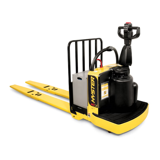
- Page 1 Hyster B262 (B60ZHD, B80ZHD) Forklift...
- Page 2 ELECTRICAL SYSTEM B60Z [C230]; B60Z [B262]; B80Z [B257] PART NO. 4096092 2200 SRM 1640...
- Page 3 • Keep the tools clean and in good condition. • Always use HYSTER APPROVED parts when making repairs. Replacement parts must meet or exceed the specifi- cations of the original equipment manufacturer. • Make sure all nuts, bolts, snap rings, and other fastening devices are removed before using force to remove parts.
-
Page 4: Table Of Contents
Control Module ..................................19 Check ..................................... 19 Remove ....................................20 Install ..................................... 20 Proximity Switch (Power Assist Steering) ..........................22 Remove ....................................22 Install ..................................... 22 Remote Control Box Switches ..............................23 Remove ....................................23 Install ..................................... 23 ©2013 HYSTER COMPANY... - Page 5 Thanks very much for your reading, Want to get more information, Please click here, Then get the complete manual NOTE: If there is no response to click on the link above, please download the PDF document first, and then click on it. Have any questions please write to me: admin@servicemanualperfect.com...
- Page 6 Table of Contents Electrical System TABLE OF CONTENTS (Continued) Troubleshooting ..................................24 This section is for the following models: (B60ZAC) [C230]; (B60ZHD) [B262]; (B80ZHD) [B257]...
-
Page 7: General
2200 SRM 1640 General General repairs to your supervisor immediately. If repair is WARNING necessary, attach a DO NOT OPERATE tag to the DO NOT make repairs or adjustments unless you control handle and disconnect the battery. have been properly trained and authorized to do so. -
Page 8: Accessing The Drive Unit Compartment
General 2200 SRM 1640 ACCESSING THE DRIVE UNIT COMPARTMENT The drive unit compartment is concealed behind a molded cover which fits securely around the drive unit and steer support to the frame. The floor mat fits snugly in the operator platform after the drive unit cover is installed. To remove the drive unit cover, first lift the corners of the floor mat and pull it out away from the drive unit. -
Page 9: Special Precautions
2200 SRM 1640 Special Precautions Special Precautions DISCHARGING THE INTERNAL erated by the MDU and brake assembly which can interfere CAPACITORS with the operation of the torque sensor. Make certain that the Electromagnetic Shield is reinstalled before operating When working with the electrical systems of the truck, it is the lift truck after servicing to prevent erratic operation of necessary to discharge the internal capacitors of the con- the power assist steering function. -
Page 10: Electrical System Checks
Electrical System Checks 2200 SRM 1640 Electrical System Checks one-piece units. Put a block in front and back of WARNING the tire or wheels touching the ground to prevent Disconnect the battery before opening the com- unexpected movement of the lift truck. partment cover or inspecting or repairing the elec- trical system. - Page 11 2200 SRM 1640 Electrical System Checks 6. The electric lift truck has a two-wire system. The than 30 percent of the battery voltage) between the bat- frame must not be a common electrical path. Check for tery and the frame, even though the resistance is very 50,000 ohms or more between each battery terminal high.
- Page 12 Electrical System Checks 2200 SRM 1640 Table 1. Voltage Checks LIFT TRUCK WILL NOT MOVE IN EITHER DIRECTION. NO FAULT IS DISPLAYED ON THE CONTROLLER. Possible Causes: 1. Battery not connected. 2. Control fuse is damaged. 3. Key switch or brake switch is damaged. 4.
-
Page 13: Calibration
2200 SRM 1640 Calibration Calibration POWER ASSIST STEERING SENSOR WARNING DO NOT interfere with the lift truck or tiller handle WARNING during the calibration cycle. If at any time a tiller handle slowly moves in one direction during startup, it is likely calibration 4. -
Page 14: Controller, Replace
Repairs 2200 SRM 1640 CONTROLLER, REPLACE Turn the key switch to the OFF position and discon- nect the battery again to continue installation. WARNING 4. Install the drive unit compartment covers. Some checks require the battery to be connected. DO NOT connect the battery until the procedure tells you to do so. -
Page 15: Contactor Coil, Check
2200 SRM 1640 Fuses CONTACTOR COIL, CHECK Disconnect coil wires. Test contactor coil using an ohmme- ter to measure the resistance. The coil should read 23 ohms ±10%. Remove and replace contactor if resistance readings indicate a short circuit in both directions or if there is an open circuit in both directions. -
Page 16: Horn
Horn 2200 SRM 1640 Horn REPLACE 5. Remove nuts and washers from bolts securing horn to frame. Remove horn from bolts. Position new horn 1. Move the truck to a safe, level location; turn the key onto bolts as removed and install washers and nut. switch to the OFF position;... -
Page 17: Brake And Interlock Switches
2200 SRM 1640 Brake and Interlock Switches Brake and Interlock Switches STANDARD STEERING 6. Connect battery and turn the key switch to the ON po- sition. 1. Position the lift truck on a level surface. Turn the key switch to the OFF position and disconnect the battery. 7. -
Page 18: Height Limit
Height Limit 2200 SRM 1640 7. Connect the battery, turn the key switch to the ON po- sition, and test for proper operation. Turn the key switch back to the OFF position and disconnect the battery again to finish repairs. 8. -
Page 19: Assemble
2200 SRM 1640 Control Handle (Standard) NOTE: It is not always necessary to remove and disas- 8. Using the remaining butterfly knob, slide the shaft out semble all the components that make up the control section of the handle. Be careful not to rotate the shaft within of the steering handle to replace a damaged part. - Page 20 Control Handle (Standard) 2200 SRM 1640 1. LOWER HALF 12. SPRING 2. UPPER HALF 13. SWITCH 3. CONTROL HANDLE CARD ASSEMBLY 14. HORN SWITCH COVER 4. SHAFT 15. SWITCH ASSEMBLY 5. BUSHING 16. LABEL 6. LH BUTTERFLY KNOB 17. LABEL 7.
-
Page 21: Control Handle (Hd Option)
2200 SRM 1640 Control Handle (HD Option) Control Handle (HD Option) DISASSEMBLE NOTE: Position the handle vertically to access the screws securing it to the base. Hold the switch while removing Remove Top Cover screws from the base. NOTE: Cover screws near the traction reverse switch are 2. -
Page 22: Remove Handle Shaft Assembly
Control Handle (HD Option) 2200 SRM 1640 6. Move the butterfly actuators as required to remove the spiral pins from the shaft (2 pins per side). 7. Remove the butterfly actuators from the shaft. 1. PIN Figure 14. Retaining Pin 1. -
Page 23: Remove The Coast Control Switches
2200 SRM 1640 Control Handle (HD Option) 3. Install the actuator and two springs into the cover. 4. Place the switch base on the cover and install the as- sembly to the handle with the two screws and washers removed during disassembly. Install Handle Shaft Assembly 1. -
Page 24: Install Throttle Sensor Assembly
Control Handle (HD Option) 2200 SRM 1640 5. Position the handle shaft assembly into the handle. 11. Install the top cover. See Install Top Cover in this sec- tion. NOTE: The pins are a slight press fit to the handle and may require slight tapping with a hammer and punch to in- Install Function Switches stall. -
Page 25: Control Module
2200 SRM 1640 Control Module 3. Hold the traction reversing actuator and springs in place in the top cover and install the traction reversing actuator into the recess in the bottom half of the han- dle. Lower the cover onto the handle base. 4. -
Page 26: Remove
Control Module 2200 SRM 1640 INSTALL 5. Reconnect 6way connector B, check pin 9 on connec- tor A for +5V. NOTE: Install new control module with the 16way con- 6. If there is no voltage at A9 (+5V), then troubleshoot nector (A) orientation toward the floor mat.
Need help?
Do you have a question about the B262 and is the answer not in the manual?
Questions and answers